ESP32 OLED clock: NTP time, big digits and a rolling animation
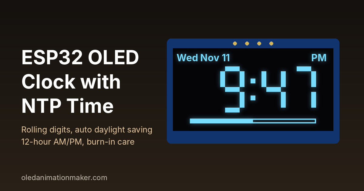
An ESP32 OLED clock is one of the best first WiFi projects. The ESP32 gets the exact time from the internet, so you never set it by hand and it changes for daylight saving by itself. This guide builds a desk clock on a cheap 0.96 inch SSD1306 screen. It has big digits that fill the display, a smooth roll when a digit changes, the date, 12-hour or 24-hour time, and a few tricks that stop the screen from wearing out.
Animated desk clocks on tiny OLEDs are popular right now. Open-source builds with retro game style clock faces, like the SmallOLED project for the ESP32-C3, have been shared widely this fall. This page gives you a simpler clock you can understand line by line, and then change into your own design.
Short version. Wire the SSD1306 to 3V3, GND, GPIO 21 (SDA) and GPIO 22 (SCL). Install the Adafruit SSD1306 library. Paste the sketch below, add your 2.4 GHz WiFi details and your time zone string, and upload. The ESP32 reads the time with NTP, draws each digit from seven filled bars, and slides a new digit in from below every time the minute changes.
What this ESP32 OLED clock shows
The middle of the screen shows the hours and minutes in tall seven-segment digits, like an old alarm clock. Each digit is 38 pixels tall, which is easy to read from across a desk. A colon between the hours and minutes blinks once a second.
The top line shows the day and date, such as "Wed Nov 11", with AM or PM on the right. A thin bar along the bottom fills up over each minute, so you can still see the seconds passing. When a digit changes, the old one slides up and out while the new one rolls in from below. It takes about a third of a second.
From 10 PM to 7 AM the screen dims. Every minute the whole picture also moves by a pixel or two. You will not notice the move, but it spreads the wear across the screen.
What you need
- An ESP32 board. A classic ESP32 DevKit V1 (ESP32-WROOM-32) costs about $6 to $10 on Amazon US. An ESP32-C3 SuperMini or ESP32-S3 DevKit works too.
- A 0.96 inch 128x64 I2C OLED with the SSD1306 chip. It has four pins: GND, VCC, SCL and SDA. Expect $5 to $8.
- Four jumper wires, female-to-female for a bare board, or a breadboard and male-to-male wires.
- A USB data cable and a phone charger to run the clock once it is finished.
- A 2.4 GHz WiFi network. Most ESP32 chips cannot connect to 5 GHz networks.
Wire the SSD1306 OLED to the ESP32
The screen uses I2C, a two-wire bus. SDA carries the data and SCL carries the clock signal that keeps both sides in step. Power the screen from the 3.3 V pin, which is the safe choice for the ESP32's pins.
| OLED pin | ESP32 DevKit V1 | ESP32-C3 SuperMini | ESP32-S3 DevKitC-1 |
|---|---|---|---|
| GND | GND | GND | GND |
| VCC | 3V3 | 3V3 | 3V3 |
| SCL | GPIO 22 | GPIO 9 | GPIO 9 |
| SDA | GPIO 21 | GPIO 8 | GPIO 8 |
| In the sketch | SDA_PIN 21, SCL_PIN 22 | SDA_PIN 8, SCL_PIN 9 | SDA_PIN 8, SCL_PIN 9 |
Read the labels on your own module before you connect power. Some boards print VCC first and GND second, and swapping those two can kill the screen. The ESP32 OLED wiring and animation guide shows the same four wires with more detail if this is your first OLED.
Install the ESP32 board and the OLED library
- In the Arduino IDE, open Tools > Board > Boards Manager. Search for esp32 and install esp32 by Espressif Systems.
- Choose your board. Pick ESP32 Dev Module for a DevKit V1. For a C3 SuperMini, pick ESP32C3 Dev Module and set USB CDC On Boot to Enabled, or the Serial Monitor stays empty.
- Open Sketch > Include Library > Manage Libraries. Search for Adafruit SSD1306 and install it. Accept the offer to install Adafruit GFX and Adafruit BusIO as well.
No NTP library is needed. The ESP32 core already declares configTzTime() and getLocalTime()
in its Arduino.h file.
The drawing calls, such as fillRect() and dim(), come from the
Adafruit SSD1306 library.
Set your time zone and daylight saving
Time servers send UTC, the world reference time. A time zone string tells the ESP32 how far you are from UTC and when your clocks go forward and back. Get this string right and the clock changes for daylight saving on its own.
| Where you live | TZ_INFO string |
|---|---|
| US Eastern (New York, Toronto) | EST5EDT,M3.2.0,M11.1.0 |
| US Central (Chicago) | CST6CDT,M3.2.0,M11.1.0 |
| US Mountain (Denver) | MST7MDT,M3.2.0,M11.1.0 |
| Arizona (no daylight saving) | MST7 |
| US Pacific (Los Angeles) | PST8PDT,M3.2.0,M11.1.0 |
| UK (London) | GMT0BST,M3.5.0/1,M10.5.0 |
| Central Europe (Berlin, Paris) | CET-1CEST,M3.5.0,M10.5.0/3 |
| Australia East (Sydney) | AEST-10AEDT,M10.1.0,M4.1.0/3 |
The sign looks backwards but is correct: "EST5" means five hours behind UTC. "M3.2.0" means the second Sunday of
March. Many online clock tutorials use configTime() with a fixed offset instead. Those clocks are an
hour wrong for half the year. The ESP32 Christmas countdown uses the
same strings, so you can reuse them in both projects.
The ESP32 OLED clock code
Paste this into a new sketch. Change the lines marked CHANGE: WiFi name and password, time zone, 12 or 24 hour mode, and the two pins if your board is not a DevKit V1.
// ESP32 OLED clock: NTP time, big 7-segment digits with a rolling animation
// Board: any ESP32 (DevKit V1, C3 SuperMini, S3). Screen: 0.96" SSD1306 128x64 I2C.
#include <WiFi.h>
#include <time.h>
#include <Wire.h>
#include <Adafruit_GFX.h>
#include <Adafruit_SSD1306.h>

// ---------- Settings ----------
const char* WIFI_SSID = "YourWiFiName";            // CHANGE: 2.4 GHz network
const char* WIFI_PASS = "YourWiFiPassword";        // CHANGE
const char* TZ_INFO   = "EST5EDT,M3.2.0,M11.1.0";  // CHANGE: your time zone string
const char* NTP_1     = "pool.ntp.org";
const char* NTP_2     = "time.nist.gov";

const bool USE_24H        = false;  // CHANGE: true for 24-hour time
const char* DATE_FORMAT   = "%a %b %d";  // CHANGE: "%a %d %b" for Wed 11 Nov
const int NIGHT_START     = 22;     // dim from 10 PM...
const int NIGHT_END       = 7;      // ...until 7 AM
const unsigned long ROLL_MS = 350;  // length of the digit roll animation

#define SDA_PIN 21                  // CHANGE: 8 on ESP32-C3 SuperMini and S3
#define SCL_PIN 22                  // CHANGE: 9 on ESP32-C3 SuperMini and S3
#define OLED_ADDR 0x3C              // CHANGE: try 0x3D if the screen stays black

#define SCREEN_W 128
#define SCREEN_H 64
Adafruit_SSD1306 display(SCREEN_W, SCREEN_H, &Wire, -1);

// ---------- Big digit layout ----------
const int DIG_W = 20;    // digit width in pixels
const int DIG_H = 38;    // digit height
const int SEG_T = 4;     // segment thickness
const int DIG_Y = 14;    // top of the digits
const int DIG_X[4] = {12, 37, 71, 96};  // x of H, H, M, M
const int BLANK = 10;    // index for an empty digit

// Segments a..g as bits 0..6 for 0-9, then blank
const uint8_t SEGMENTS[11] = {
  0x3F, 0x06, 0x5B, 0x4F, 0x66, 0x6D, 0x7D, 0x07, 0x7F, 0x6F, 0x00
};

int shownDigit[4] = {BLANK, BLANK, BLANK, BLANK};  // digit on screen now
int oldDigit[4]   = {BLANK, BLANK, BLANK, BLANK};  // digit rolling away
unsigned long rollStart[4] = {0, 0, 0, 0};

void drawDigit(int x, int y, int d) {
  uint8_t s = SEGMENTS[d];
  int mid = y + (DIG_H - SEG_T) / 2;           // top of the middle bar
  int half = (DIG_H - 3 * SEG_T) / 2;          // length of a side bar
  if (s & 0x01) display.fillRect(x + SEG_T, y, DIG_W - 2 * SEG_T, SEG_T, SSD1306_WHITE);                  // a top
  if (s & 0x02) display.fillRect(x + DIG_W - SEG_T, y + SEG_T, SEG_T, half, SSD1306_WHITE);               // b upper right
  if (s & 0x04) display.fillRect(x + DIG_W - SEG_T, mid + SEG_T, SEG_T, half, SSD1306_WHITE);             // c lower right
  if (s & 0x08) display.fillRect(x + SEG_T, y + DIG_H - SEG_T, DIG_W - 2 * SEG_T, SEG_T, SSD1306_WHITE);  // d bottom
  if (s & 0x10) display.fillRect(x, mid + SEG_T, SEG_T, half, SSD1306_WHITE);                             // e lower left
  if (s & 0x20) display.fillRect(x, y + SEG_T, SEG_T, half, SSD1306_WHITE);                               // f upper left
  if (s & 0x40) display.fillRect(x + SEG_T, mid, DIG_W - 2 * SEG_T, SEG_T, SSD1306_WHITE);                // g middle
}

// Draw one digit position, rolling the old digit up and the new one in
void drawRollingDigit(int i, int x, int y) {
  unsigned long t = millis() - rollStart[i];
  if (t >= ROLL_MS) {
    drawDigit(x, y, shownDigit[i]);
    return;
  }
  int travel = DIG_H + 4;                      // distance one digit moves
  int offset = (int)(t * travel / ROLL_MS);
  drawDigit(x, y - offset, oldDigit[i]);
  drawDigit(x, y + travel - offset, shownDigit[i]);
}

void setDigit(int i, int d) {
  if (d == shownDigit[i]) return;
  oldDigit[i] = shownDigit[i];
  shownDigit[i] = d;
  rollStart[i] = millis();
}

void showMessage(const char* line1, const char* line2) {
  display.clearDisplay();
  display.setTextSize(1);
  display.setTextColor(SSD1306_WHITE);
  display.setCursor(0, 20);
  display.println(line1);
  display.setCursor(0, 34);
  display.println(line2);
  display.display();
}

void setup() {
  Serial.begin(115200);
  Wire.begin(SDA_PIN, SCL_PIN);
  if (!display.begin(SSD1306_SWITCHCAPVCC, OLED_ADDR)) {
    Serial.println("SSD1306 not found. Check wiring and address.");
    while (true) delay(1000);
  }

  showMessage("Connecting WiFi...", WIFI_SSID);
  WiFi.mode(WIFI_STA);
  WiFi.begin(WIFI_SSID, WIFI_PASS);
  unsigned long start = millis();
  while (WiFi.status() != WL_CONNECTED) {
    delay(250);
    if (millis() - start > 30000) {       // give up after 30 s and retry
      Serial.println("WiFi failed, restarting");
      ESP.restart();
    }
  }
  Serial.print("WiFi OK, IP ");
  Serial.println(WiFi.localIP());

  showMessage("Getting time...", NTP_1);
  configTzTime(TZ_INFO, NTP_1, NTP_2);    // time zone + start NTP
  struct tm now;
  while (!getLocalTime(&now, 10000)) {
    Serial.println("Still waiting for NTP time");
  }
  Serial.println(&now, "Local time: %A %B %d %Y %I:%M:%S %p");
}

void loop() {
  struct tm now;
  if (!getLocalTime(&now, 1000)) return;

  // Night mode: lower the brightness
  static int dimmed = -1;
  int wantDim = (now.tm_hour >= NIGHT_START || now.tm_hour < NIGHT_END) ? 1 : 0;
  if (wantDim != dimmed) {
    display.dim(wantDim == 1);
    dimmed = wantDim;
  }

  // Hours in 12 or 24 hour format
  int hour = now.tm_hour;
  if (!USE_24H) {
    hour = hour % 12;
    if (hour == 0) hour = 12;              // 0:xx is 12:xx AM
  }
  int h1 = hour / 10;
  if (!USE_24H && h1 == 0) h1 = BLANK;     // " 9:05" instead of "09:05"
  setDigit(0, h1);
  setDigit(1, hour % 10);
  setDigit(2, now.tm_min / 10);
  setDigit(3, now.tm_min % 10);

  // Burn-in protection: move everything by up to 2 pixels each minute
  int sx = (now.tm_min % 5) - 2;           // -2..2
  int sy = ((now.tm_min / 5) % 3) - 1;     // -1..1
  int y = DIG_Y + sy;

  display.clearDisplay();
  for (int i = 0; i < 4; i++) {
    drawRollingDigit(i, DIG_X[i] + sx, y);
  }
  // Hide the parts of rolling digits that move outside the digit window
  display.fillRect(0, 0, SCREEN_W, y, SSD1306_BLACK);
  display.fillRect(0, y + DIG_H, SCREEN_W, SCREEN_H - (y + DIG_H), SSD1306_BLACK);

  // Blinking colon
  if (now.tm_sec % 2 == 0) {
    display.fillRect(62 + sx, y + 10, 4, 4, SSD1306_WHITE);
    display.fillRect(62 + sx, y + 24, 4, 4, SSD1306_WHITE);
  }

  // Top line: date on the left, WiFi warning and AM/PM on the right
  char buf[20];
  strftime(buf, sizeof(buf), DATE_FORMAT, &now);
  display.setTextSize(1);
  display.setTextColor(SSD1306_WHITE);
  display.setCursor(2 + sx, 2 + sy);
  display.print(buf);
  if (WiFi.status() != WL_CONNECTED) {
    display.setCursor(74 + sx, 2 + sy);
    display.print("NO NET");
  }
  if (!USE_24H) {
    display.setCursor(114 + sx, 2 + sy);
    display.print(now.tm_hour < 12 ? "AM" : "PM");
  }

  // Bottom: a bar that fills up over each minute
  int barW = (constrain(now.tm_sec, 0, 59) * 104) / 59;
  display.drawRect(12 + sx, 57 + sy, 104, 4, SSD1306_WHITE);
  display.fillRect(12 + sx, 57 + sy, barW, 4, SSD1306_WHITE);

  display.display();   // nothing appears until this is called
  delay(20);
}
What you should see
- Open Tools > Serial Monitor at 115200 baud, then upload.
- The OLED shows "Connecting WiFi..." with your network name under it.
- Next it shows "Getting time...". The Serial Monitor prints your IP address and a line like "Local time: Wednesday November 11 2026 09:47:30 PM".
- The four digits roll up into place, the colon starts blinking and the bottom bar starts filling.
- At the top of the next minute, only the digits that change roll. At 9:59 to 10:00, three of them roll together.
If the time in the Serial Monitor is off by whole hours, the time zone string is wrong. Fix that before anything else, because the screen uses the same time.
How the big digits and the roll animation work
Seven bars make a digit
Text size 3 in Adafruit GFX gives blocky, stair-stepped numbers. This sketch draws its own digits instead. Each digit
is made of up to seven bars, called segments, named a to g. The SEGMENTS array stores one byte per
digit. Each bit says whether one bar is lit.
For example, 1 is 0x06, which lights only the two right-hand bars. drawDigit() checks each
bit and draws a filled rectangle for every bar that is on. A gap at each corner gives the classic segmented look.
Index 10 has no bars lit. The clock uses it to hide the leading zero, so 9:05 does not show as 09:05.
The rolling animation
The sketch remembers which digit is on screen in each of the four places. When a new minute gives a different
digit, setDigit() saves the old one and notes the time with millis().
For the next 350 ms, drawRollingDigit() draws the old digit moving up and the new digit just below it.
The distance moved grows with the time passed. Parts that slide outside the digit area are painted over with two
black rectangles. Then the date and the seconds bar are drawn on top. Change ROLL_MS to make the roll
faster or slower.
12-hour time and AM/PM
getLocalTime() fills a tm structure with the hour from 0 to 23. For 12-hour time the code
takes the hour modulo 12, then shows 12 when the result is 0. Midnight is 12 AM and noon is 12 PM. The label is AM
whenever tm_hour is below 12.
How accurate is an ESP32 NTP clock?
configTzTime() starts SNTP, the simple form of NTP, in the background. After the first answer, the ESP32
counts time with its own crystal. It then asks the server again every hour. That interval is the default
LWIP_SNTP_UPDATE_DELAY of 3,600,000 ms in the
ESP-IDF network settings,
which the Arduino core is built on.
So the clock is corrected every hour and stays within a fraction of a second of the real time. If the WiFi drops, it keeps running on the crystal. The top line shows "NO NET" so you know it is not being corrected. The ESP32 tries to reconnect by itself.
You do not need an RTC module, a separate clock chip with its own battery. Add one, such as a DS3231, only if the clock must show the right time after a power cut with no WiFi at all.
Stop OLED burn-in on a clock that runs all day
OLED pixels make their own light, and each one ages a little for every hour it is lit. A clock is the worst case. The same bars of the same digits stay on for months, and they can leave a faint ghost image. Three habits keep a clock screen looking new:
- Dim it.
display.dim(true)sets the contrast to its lowest level. The sketch does this fromNIGHT_STARTtoNIGHT_END. - Move it. The sketch shifts everything by up to 2 pixels left or right and 1 pixel up or down each minute. No single pixel stays on all the time.
- Turn it off when nobody is looking. Send
display.ssd1306_command(SSD1306_DISPLAYOFF)to blank the panel, andSSD1306_DISPLAYONto wake it. The ESP32 keeps the time while the screen is off.
For a bedroom clock you might prefer it fully off at night. Replace the display.dim() line with the two
commands above, chosen by wantDim. A dark screen also saves power: the
OLED power consumption guide shows how the current
drops as fewer pixels are lit.
Make the ESP32 clock your own
- 24-hour time: set
USE_24Hto true. The leading zero comes back, and the AM/PM label goes away. - European date: set
DATE_FORMATto"%a %d %b"for "Wed 11 Nov". Anystrftime()code works, but keep it under about 12 characters. - Thicker digits: set
SEG_Tto 5 andDIG_Hto 39.DIG_Hminus three timesSEG_Tmust be an even number, or a one-pixel gap appears in the bars. - Gauges and sensor values: swap the seconds bar for a temperature reading. The OLED dashboard guide has ready-made bars and gauges.
- A little animation on the hour: draw a short loop in the OLED Animation Maker, export the frames, and play them for a few seconds when
tm_minis 0.
You can try the sketch before you buy parts. The Wokwi SSD1306 simulator guide shows how to run ESP32 code with an OLED in the browser. In Wokwi, use the network name Wokwi-GUEST with an empty password.
Troubleshooting the ESP32 OLED clock
- Problem: stuck on "Connecting WiFi". Why: the network is 5 GHz only, or the name or password has a typo. Both are case sensitive. Fix: use the 2.4 GHz network, or test with a phone hotspot.
- Problem: stuck on "Getting time". Why: the network blocks NTP on UDP port 123. Some school, office and guest networks do this. Fix: test on a phone hotspot, then ask for port 123 to be opened.
- Problem: the time is off by whole hours. Why: a wrong or missing time zone string. Fix: copy the exact string from the table and check the time in the Serial Monitor.
- Problem: the clock jumps an hour in March or November. Why: the string has no daylight saving rules, such as plain "EST5". Fix: use the full string with the parts after the commas.
- Problem: the screen stays black. Why: SDA and SCL are swapped, the pins in the sketch do not match the wiring, or the address is 0x3D. Fix: check the wires, then try 0x3D. The SSD1306 blank screen fixes include an I2C scanner.
- Problem: a noisy stripe down one edge and the picture is shifted. Why: it is a 1.3 inch SH1106 screen, not an SSD1306. Fix: switch to the Adafruit SH110X library. The SH1106 vs SSD1306 guide explains how to tell them apart.
- Problem: the roll looks jerky. Why: the I2C bus is slow, or other code in
loop()takes a long time. Fix: keep extra work short, and do not add a longdelay(). One full frame takes roughly 25 ms at the library's default 400 kHz bus speed. - Problem: the board restarts with "Brownout detector was triggered". Why: WiFi start-up pulls a burst of current the USB port cannot supply. Fix: use a short cable and a wall charger, not a laptop hub.
Put the clock in a case
A bare board on a desk collects dust and gets knocked about. A small 3D printed stand fixes that. A 0.96 inch OLED module is about 27 mm (just over 1 inch) square, with the glass near the top edge. Design a front with a window about 24 x 13 mm, tilt it back by 10 to 15 degrees, and leave a slot for the USB cable.
Black or dark gray filament hides the edges of the module best. Hold the board with two M2 screws or a dab of hot glue on the back of the PCB, never on the glass. The same shell works for the ESP32 desk robot with OLED eyes, so you can print one design for both projects.
Next steps
- Turn the clock into a countdown with the ESP32 Christmas countdown sketch.
- Learn more drawing calls, such as circles for an analog face, in the OLED shapes guide.
- Make a startup logo for the clock in the OLED Animation Maker and show it before "Connecting WiFi".
Frequently asked questions
Does an ESP32 clock need an RTC module?
No, as long as it has WiFi. The ESP32 gets the time from an internet time server with NTP and then keeps counting by itself. Add a DS3231 RTC module only if the clock must start without any network.
How often does the ESP32 sync with the NTP server?
Once an hour by default. The ESP-IDF setting behind the Arduino core asks the time server again every 3,600,000 ms, so a clock that stays on WiFi is corrected every hour.
How do I show 12-hour time with AM and PM?
Take the hour modulo 12 and show 12 when the result is 0. The hour is AM when tm_hour is below 12. In the sketch on this page, set USE_24H to false and it does this for you.
Will an OLED clock burn in?
It can, because the same pixels stay lit for months. Dim the screen at night, turn it off when nobody is there, and move the picture by a pixel or two every minute. The sketch on this page does the dimming and the moving.
Can I use a 1.3 inch SH1106 OLED for the clock?
Yes, with a different library. Install Adafruit SH110X, use Adafruit_SH1106G in place of Adafruit_SSD1306, call begin(0x3C, true), change SSD1306_WHITE and SSD1306_BLACK to SH110X_WHITE and SH110X_BLACK, and use setContrast(0) in place of dim(true).
Related guides
- ESP32 Christmas countdown on an SSD1306 OLED
- ESP32 OLED animation: SSD1306 wiring and code
- Fix an SSD1306 OLED blank screen
- SH1106 vs SSD1306: differences and how to tell
- ESP32 desk robot with OLED eyes and touch moods
Free tools: Lithophane Maker for flat, curved, heart, round and cylinder lamp lithophanes, the Shadow Box Lamp Generator for wall shadow lamps, Text to STL for names and keychains, and 3MF to Web to show your prints on a website. See all tools.