Draw OLED Shapes and Get Arduino Code: drawCircle, drawRect, drawLine
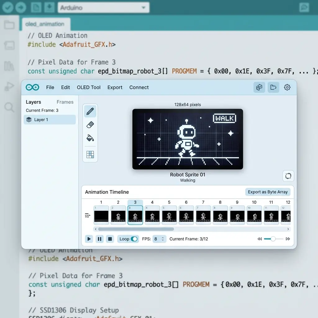
Let me share something that took me way too long to figure out. For months, every OLED screen I made—even simple ones with just a border and some text—got exported as a massive bitmap byte array. A simple battery indicator with a rectangle outline became 1,024 bytes of hex code that I couldn't read or edit. If I wanted to nudge the rectangle two pixels to the left, I had to redraw the whole thing and regenerate. It drove me nuts.
Then it hit me: for screens made of shapes and text, you don't need a bitmap at all. The Adafruit GFX library
(and U8g2) have built-in functions like drawCircle, drawRect, and drawLine that draw
shapes directly. This is called vector code or "GFX primitives," and it's how experienced makers hand-write
their OLED UIs. The code is tiny, readable, and you can tweak any coordinate right in your sketch.
The problem? Manually figuring out the X/Y coordinates for every shape is tedious. You draw a circle, guess the center point,
upload, see it's in the wrong spot, adjust, upload again... sound familiar? That's why I added a Vector code mode
to the free OLED animation maker. You draw shapes visually, and it spits out
clean drawCircle, drawRect, and drawLine calls—exactly like hand-written code, but without
the guesswork. This guide explains when to use it and how.
Bitmap code vs vector code: what's the difference?
Understanding this distinction is the key to writing efficient OLED code. There are two fundamentally different ways to put graphics on your screen, and each is better for certain situations.
Bitmap code (drawBitmap)
With bitmap code, every single pixel gets packed into a PROGMEM byte array, and the whole thing is drawn at once with
drawBitmap(). Think of it like a photograph—it captures the exact state of every pixel. This is the right choice for:
- Animations – multi-frame playback is cleaner and faster as bitmaps
- Imported GIFs and PNGs – photos have no "shapes" to recover, so bitmap is exact
- Dithered images – complex shading needs pixel-level control
- Detailed pixel art – keep it as a bitmap for perfect fidelity
Vector code (GFX primitives)
With vector code, each shape becomes a readable function call. A rectangle is drawRect(x, y, width, height). A circle
is drawCircle(x, y, radius). It's like giving instructions ("draw a circle here, this big") rather than specifying
every pixel. This is perfect for:
- Static UI screens – menus, dashboards, status displays made of geometric shapes
- Editable layouts – change a coordinate or color directly in your sketch, no regeneration needed
- Memory efficiency – a few lines of code instead of a 1KB array
- Readable code – you (and others) can understand what the screen shows just by reading the code
Here's a real comparison: A simple screen with a border rectangle, a divider line, and a circle. As a bitmap, that's 1,024 bytes of unreadable hex. As vector code, it's about 4 lines you can read and edit instantly. For UI screens, vector wins easily.
How to draw shapes and export GFX code (step by step)
- Open the tool and click the ✏️ Draw tab.
- Use the Line, Rect, Filled Rect, Circle, and Text tools to compose your screen. Just click and drag to place each shape.
- Grab the ✋ Move tool to drag shapes around, and pull the corner or edge handles to resize any shape, icon, or text block. This is where the visual editing really shines—no coordinate guessing.
- Click ⚡ Get the Code, then flip the header toggle from Bitmap to Vector.
- Copy or download the Arduino
.inofile (Adafruit SSD1306 or U8g2) or MicroPython output.
The beauty here is that you design visually—dragging and resizing until it looks right—but get clean, hand-editable code as the output. Best of both worlds.
Example: what the generated Adafruit GFX code looks like
A circle, a rectangle, and a line drawn on a 128×64 SSD1306 export like this:
void renderFrame0() {
  display.clearDisplay();
  display.drawRect(40, 20, 30, 15, SSD1306_WHITE);
  display.drawLine(10, 50, 60, 50, SSD1306_WHITE);
  display.drawCircle(90, 30, 10, SSD1306_WHITE);
  display.display();
}
See how readable that is? You can immediately tell there's a rectangle at position (40, 20), a line, and a circle at (90, 30). Want to move the circle? Just change those numbers. No regenerating bitmaps, no hex editing.
Switch the library to U8g2 and the same drawing becomes u8g2.drawFrame(),
u8g2.drawLine(), and u8g2.drawCircle(). Choose MicroPython and you get
display.rect(), display.line(), and display.ellipse() via framebuf. Same shapes, your
choice of platform.
The smart hybrid: shapes AND images together
Here's a clever detail. Vector mode is actually a hybrid. Hand-drawn shapes and text become clean primitives,
while anything that has no clean geometry—imported images, GIF frames, freehand strokes, and detailed icons—gets packed into a
compact drawBitmap() call.
So imagine a screen with a battery outline, a text label, and a detailed company logo. The tool gives you crisp
drawRect and println calls for the battery and label, plus one small bitmap for the logo that can't be
represented as simple shapes. You always get pixel-faithful output without wasting memory on things that could be simple shapes.
Bonus: 200,000+ icons ready to drop on your canvas
One feature I'm genuinely proud of: click the 🔣 icon button in the Draw toolbar and you can search a library of over 200,000 open-source monochrome icons. We're talking Material Icons, Tabler, Lucide, Bootstrap icons, pixel-art sets, and tons more (all via Iconify).
Drop any icon onto your canvas, then move and resize it like any other layer. This is perfect for status bars (WiFi, battery, signal icons), weather glyphs, navigation symbols, and UI mockups. Each placed icon exports as an efficient OLED bitmap. No more hunting for icon byte arrays or drawing symbols pixel by pixel.
When should you stick with bitmap mode?
Vector mode is awesome for UI screens, but it's not always the right choice. Use bitmap mode (the default) when you're working with:
- Animations – multi-frame playback is far cleaner and faster as bitmaps
- Photos or dithered images – there are no shapes to recover, so bitmap is exact
- Detailed pixel art – keep it as a bitmap for perfect fidelity
That's why bitmap stays the default—it's the right choice most of the time. Vector is a one-click toggle for when you're building shape-based UI screens and want clean, editable code.
Popular searches: draw oled shapes arduino · drawcircle arduino oled · drawrect ssd1306 · oled gfx code generator · adafruit gfx primitives · u8g2 draw shapes · oled icon library · arduino oled code generator
Frequently asked questions
What's the difference between drawRect and fillRect?
drawRect draws just the outline of a rectangle (a hollow box). fillRect draws a solid filled
rectangle. The same applies to circles: drawCircle is an outline, fillCircle is solid. Use outlines for
borders and frames, fills for solid buttons or indicators.
Does vector code use less memory than bitmaps?
Usually yes, for shape-based screens. A few GFX function calls take far less flash memory than a 1KB bitmap array. But for photos or complex pixel art, bitmaps are actually more efficient since there are no simple shapes to extract.
Can I mix shapes and text on the same screen?
Absolutely. That's exactly what vector mode is built for. Combine rectangles, circles, lines, and text labels to create complete UI screens—dashboards, menus, status displays. Each element exports as its own readable GFX call.
Are the Iconify icons free to use in commercial projects?
Most are, but licenses vary by icon set (MIT, Apache, CC-BY, etc.). Check the specific icon set's license before using it commercially. Many sets like Material and Tabler are very permissive.
Why is my circle cut off even though the preview looked fine?
drawCircle uses a center and a radius, not a bounding box. A circle at (120, 32) with radius 16 runs to x = 136, past the 127 edge of a 128-wide panel. Keep centerX ± radius inside 0–127 and centerY ± radius inside 0–63.
Does vector export still cost 1024 bytes per frame?
No. A full-screen bitmap is 1024 bytes because 128×64 pixels pack to one bit each. A handful of drawRect and drawCircle calls are just instructions. Memory jumps back up only for layers that stay as drawBitmap, such as a detailed icon.
What is the origin of drawRect compared with drawCircle?
drawRect(x, y, w, h) starts at the top-left corner and the width and height extend right and down. drawCircle(cx, cy, r) is the center. Mixing those up by treating a circle center as a corner is the usual reason a knob sits too far down and right.
Draw shapes → get Arduino code, free
Vector or bitmap export, a 200k+ icon library, move & resize on canvas — no install.
Open Tool →Worked example: a status badge in GFX calls
This is a static “link up” badge I use to check that vector export matches the glass. It is not an animation, so bitmap mode would spend 1024 bytes to store a nearly empty 128×64 frame. Four primitives do the same picture and stay editable in the sketch.
Canvas is 128 by 64. I want a card inset by 4 pixels, a 12-pixel status dot in the left of the card, a horizontal rule under a title, and a one-line caption. Planning the numbers before export:
- Card outline:
drawRect(4, 4, 120, 56). The right edge lands on x = 4+120-1 = 123, the bottom on y = 59, so the stroke stays on-screen. - Status dot: filled circle centered at (18, 18) with radius 6. Extents are x 12–24 and y 12–24, inside the card’s padding.
- Title rule:
drawLine(28, 28, 116, 28). It starts to the right of the dot and stops before the card’s right stroke. - Caption:
setCursor(28, 36), text size 1, which is 6×8 pixels. “LINK OK” is 7 characters, 42 pixels wide, ending near x = 70.
display.clearDisplay();
display.drawRect(4, 4, 120, 56, SSD1306_WHITE);
display.fillCircle(18, 18, 6, SSD1306_WHITE);
display.drawLine(28, 28, 116, 28, SSD1306_WHITE);
display.setTextSize(1);
display.setTextColor(SSD1306_WHITE);
display.setCursor(28, 36);
display.print(F("LINK OK"));
display.display();
On U8g2 the same geometry is drawFrame(4, 4, 120, 56), drawDisc(18, 18, 6), and drawLine. On an SH1106, prefer a driver that applies the column offset of 2 rather than adding 2 to every number yourself. If you do add it by hand, add it to every x, including the circle center and the text cursor, or the dot and the label drift apart.
Wiring for the upload check is the usual I²C map: Uno A4/A5, ESP32 GPIO 21/GPIO 22, ESP8266 D2/D1, address 0x3C. Draw this badge with begin before you drop in a 1024-byte logo. If the rectangle is clipped, fix coordinates first. If the whole badge is missing, fix the bus.
Order matters when shapes overlap. fillCircle after drawRect covers the card stroke if the dot sits on the border. Draw fills first, then outlines, then text. A filled rect used as a highlight will erase text you printed earlier in the same frame. There is no undo inside the buffer except drawing black over the mistake or calling clearDisplay and starting the frame again.
Troubleshooting shape export
- Circle becomes a blob in the corner. The call was given a corner and a diameter.
drawCirclewants center x, center y, and radius. Half the width, and move the center to corner plus radius. - Rectangle is one pixel too wide and wraps or clips. Width is not “right minus left.” A rect from x = 0 with width 128 covers columns 0–127. Width 129 is off the panel. The badge above uses width 120 on purpose.
- Preview matches, hardware is blank. Vector code still needs
clearDisplayand onedisplay(). Export includes those in a full sketch; a fragment pasted intoloopwithout them will not show. - Icon looks crisp, hand-drawn rect is jagged. That is expected. Icons leave vector mode as small bitmaps. Shapes stay as primitives. Do not convert the whole screen to a bitmap just to match the icon’s edges.
- Text sits on the line. Size-1 text is 8 pixels tall and the cursor is the top of the glyph. If the rule is at y = 28, start the caption at y = 32 or lower, not y = 28.
- SH1106 badge is nudged right with the right stroke missing. The controller’s visible window starts at column 2 of a 132-wide buffer. Select SH1106 in the tool, or use an SH1106 driver, instead of mixing an SSD1306 init with these 128-wide coordinates.