Arduino OLED 128x64 I2C Example — SSD1306 Wiring + Working Code
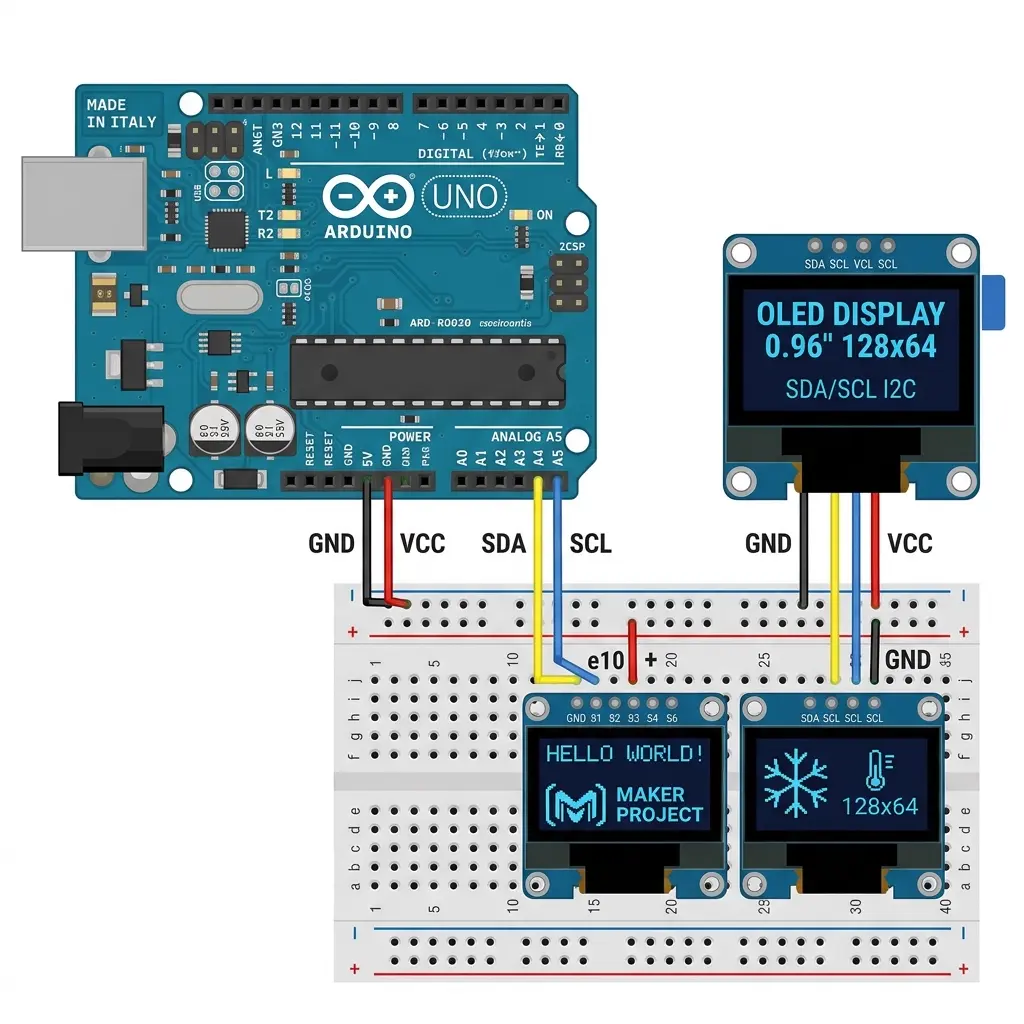
This guide is a practical Arduino OLED 128x64 I2C example: wire a 0.96" SSD1306, install the right libraries, then upload copy-paste sketches that actually work. If your screen is blank, the I2C scanner and troubleshooting sections below usually fix it in a few minutes.
You will learn how to interface an OLED with Arduino (Uno, Nano, Mega, or ESP32), run
Hello World text, draw shapes, scroll text, and diagnose the most common failures — wrong address
(0x3C vs 0x3D), wiring mistakes, and forgetting display.display().
- I2C wiring pin table (Uno / Nano / Mega / ESP32)
- Install Adafruit SSD1306 + GFX
- Hello World sketch (copy-paste)
- I2C scanner for blank screens
- Shapes example and scrolling text
- Troubleshooting + FAQ
What is a 0.96 inch SSD1306 OLED?
The 0.96-inch SSD1306 OLED is the most common small display for Arduino projects. Resolution is usually 128×64 pixels (sometimes 128×32). It talks over I2C with four wires: VCC, GND, SDA, SCL. Pixels are monochrome (on/off), which looks sharp and uses little power.
Common variants: blue, white, or yellow-blue split. Controllers may be SSD1306 or the look-alike SH1106 — wrong driver = shifted image.
Step 1: I2C wiring pin table
Use this pin map for a 4-pin I2C OLED module:
| OLED pin | Arduino Uno / Nano | Arduino Mega | ESP32 |
|---|---|---|---|
| VCC | 5V (or 3.3V if marked) | 5V / 3.3V | 3.3V |
| GND | GND | GND | GND |
| SDA | A4 | 20 | GPIO 21 |
| SCL | A5 | 21 | GPIO 22 |
Default I2C address is usually 0x3C. Some 128×64 boards use 0x3D.
If the display stays blank, jump to the I2C scanner.
Step 2: Install libraries
In Arduino IDE → Sketch → Include Library → Manage Libraries, install:
- Adafruit GFX Library — text, lines, circles
- Adafruit SSD1306 — display driver
Optional: U8g2 if you prefer that library later for fonts and animations.
Step 3: Arduino OLED 128x64 I2C Hello World (copy-paste)
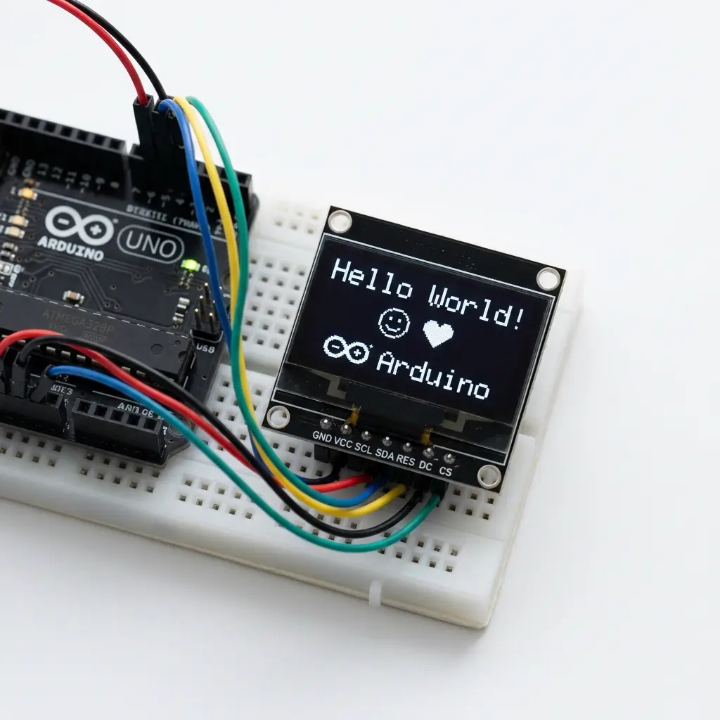
This is the sketch most people want when they search for an
Arduino OLED 128x64 I2C example. Create a new sketch, paste it, select your board and port, then Upload.
If nothing appears, change 0x3C to 0x3D.
#include <Wire.h>
#include <Adafruit_GFX.h>
#include <Adafruit_SSD1306.h>

#define SCREEN_WIDTH 128
#define SCREEN_HEIGHT 64
#define OLED_RESET    -1
#define SCREEN_ADDRESS 0x3C   // try 0x3D if blank

Adafruit_SSD1306 display(SCREEN_WIDTH, SCREEN_HEIGHT, &Wire, OLED_RESET);

void setup() {
  Serial.begin(9600);

  if (!display.begin(SSD1306_SWITCHCAPVCC, SCREEN_ADDRESS)) {
    Serial.println(F("SSD1306 allocation failed"));
    for (;;); // stop here if OLED not found
  }

  display.clearDisplay();
  display.setTextSize(1);
  display.setTextColor(SSD1306_WHITE);
  display.setCursor(0, 0);
  display.println(F("Hello World!"));
  display.println(F("SSD1306 128x64"));
  display.println(F("I2C example"));
  display.display();  // required — nothing shows without this
}

void loop() {
  // static text — nothing to update
}
Key functions you will reuse: clearDisplay(), setTextSize(),
setCursor(x, y), println(), and always display() to push pixels to the screen.
You can also open the library demo: File → Examples → Adafruit SSD1306 → ssd1306_128x64_i2c
and set SCREEN_ADDRESS the same way.
Step 4: I2C scanner (fix blank OLED)
If Hello World fails, do not guess the address. Upload this scanner and open
Tools → Serial Monitor at 9600 baud. You should see something like
I2C device found at address 0x3C.
#include <Wire.h>

void setup() {
  Wire.begin();
  Serial.begin(9600);
  while (!Serial); // wait on Leonardo / some boards
  Serial.println(F("I2C Scanner"));
}

void loop() {
  byte error, address;
  int nDevices = 0;

  Serial.println(F("Scanning..."));

  for (address = 1; address < 127; address++) {
    Wire.beginTransmission(address);
    error = Wire.endTransmission();

    if (error == 0) {
      Serial.print(F("I2C device found at 0x"));
      if (address < 16) Serial.print('0');
      Serial.println(address, HEX);
      nDevices++;
    }
  }

  if (nDevices == 0) {
    Serial.println(F("No I2C devices found — check SDA/SCL/power"));
  } else {
    Serial.println(F("Done."));
  }

  delay(5000);
}
No devices found? Recheck SDA/SCL (swapped pins are common), power, and ground. On ESP32, confirm you are using the pins you expect (often 21/22).
Step 5: Draw shapes (GFX example)
Once text works, shapes unlock dashboards and menus. Paste this after a successful Hello World setup
(same includes and display.begin as above):
void setup() {
  if (!display.begin(SSD1306_SWITCHCAPVCC, 0x3C)) {
    for (;;);
  }

  display.clearDisplay();

  display.drawRect(0, 0, 128, 64, SSD1306_WHITE);   // border
  display.fillRect(10, 10, 40, 20, SSD1306_WHITE);  // filled box
  display.drawCircle(90, 32, 18, SSD1306_WHITE);    // circle
  display.drawLine(0, 63, 127, 0, SSD1306_WHITE);   // diagonal

  display.setTextSize(1);
  display.setTextColor(SSD1306_WHITE);
  display.setCursor(10, 40);
  display.print(F("GFX shapes"));
  display.display();
}

void loop() {}
For visual layout without guessing coordinates, see the draw OLED shapes guide.
Step 6: Scrolling text example
Hardware scroll is built into Adafruit SSD1306. This sketch shows text, then scrolls it left:
void setup() {
  if (!display.begin(SSD1306_SWITCHCAPVCC, 0x3C)) {
    for (;;);
  }

  display.clearDisplay();
  display.setTextSize(2);
  display.setTextColor(SSD1306_WHITE);
  display.setCursor(0, 20);
  display.println(F("Scroll me"));
  display.display();

  display.startscrollleft(0x00, 0x0F); // scroll full display
}

void loop() {
  // hardware scroll runs until stopscroll()
}
For custom motion (sensors, menus), move the X cursor yourself and use millis() instead of
delay() so the board stays responsive.
Step 7: Images and animations (next step)
Static logos use drawBitmap() with a PROGMEM byte array. Multi-frame animations are tedious by hand —
convert frames once, then play them in a loop. Dedicated guides:
Troubleshooting: OLED blank or garbled
- Completely blank. Wrong I2C address → run the scanner. Also check SDA/SCL and power.
- Garbled or shifted image. Likely SH1106 with SSD1306 code — see SH1106 vs SSD1306.
- Flicker. Call
display.display()only when content changes. - "SSD1306 allocation failed". Display not responding — wiring or address.
- Code uploads but nothing shows. You forgot
display.display().
Faster path: generate animations in the browser
When you are ready for multi-frame animations (not just Hello World), use the free OLED animation maker to preview frames and export Adafruit SSD1306, U8g2, or MicroPython code.
Next: animate your OLED without hand-writing arrays
100+ templates · GIF import · WebSerial preview · SSD1306 & SH1106
Open oledanimationmaker.com →FAQ
Which pins for I2C OLED on Arduino Uno?
SDA → A4, SCL → A5, VCC → 5V, GND → GND.
Why is my Arduino OLED blank?
Try address 0x3D instead of 0x3C, run the I2C scanner, and confirm you call display.display().
What is the I2C address of a 0.96" SSD1306?
Usually 0x3C; some 128×64 modules use 0x3D. Scanner confirms it.
What libraries do I need?
Adafruit SSD1306 + Adafruit GFX from Library Manager.
SSD1306 vs SH1106 — which do I have?
See our SH1106 vs SSD1306 guide. Wrong driver = shifted image.
Where do SDA and SCL go on an ESP8266 NodeMCU?
D2 is SDA (GPIO4) and D1 is SCL (GPIO5). Power the module from 3.3V. Call Wire.begin(D2, D1) before display.begin. A Uno sketch that only uses A4 and A5 will upload and then show a black panel on NodeMCU.
What does OLED_RESET -1 mean in the Hello World sketch?
It means no Arduino pin is connected to RES. Four-pin I2C boards tie reset on the PCB. Pass -1. If you pass a GPIO and that pin sits low, the chip can ACK on the scanner and the glass stays black.
I have a 128×32 module. Why is the text cut in half?
The constructor height must be 32, not 64: Adafruit_SSD1306 display(128, 32, &Wire, -1). A 64-pixel buffer on a 32-pixel panel draws past the glass. The I2C address is still usually 0x3C.
begin() prints allocation failed on an Uno that scanned 0x3C. Now what?
The bus works and the 1024-byte framebuffer did not fit, or begin used the wrong address. Confirm Tools → Board, close a second display object, and match 0x3C or 0x3D. On ESP32 this SRAM error is rare; on Uno two full displays are about 2 KB and often will not allocate.
A three-line status screen that updates on a timer
Hello World proves the wires. The sketch students actually keep is a small status block: a title, a sensor line, and a one-line hint, redrawn twice a second so I2C is not busy the rest of the time. This stays on the same constructor as Step 3 — 128×64, reset -1, address 0x3C unless your scanner printed 0x3D.
uint32_t lastDraw = 0;

void drawStatus(int tempC, bool heaterOn) {
  display.clearDisplay();
  display.setTextSize(1);
  display.setTextColor(SSD1306_WHITE);
  display.setCursor(0, 0);
  display.print(F("Bench status"));
  display.drawLine(0, 10, 127, 10, SSD1306_WHITE);

  display.setTextSize(2);
  display.setCursor(0, 16);
  display.print(tempC);
  display.print(F(" C"));

  display.setTextSize(1);
  display.setCursor(0, 44);
  display.print(heaterOn ? F("Heater ON") : F("Heater idle"));
  display.setCursor(0, 56);
  display.print(F("I2C 0x3C"));
  display.display();
}

void loop() {
  if (millis() - lastDraw < 500) return;
  lastDraw = millis();
  int tempC = 24;          // replace with your sensor
  bool heaterOn = tempC < 22;
  drawStatus(tempC, heaterOn);
}
Call drawStatus once at the end of setup so the glass is not blank until the first 500 ms elapses. The 500 ms gap is the whole lesson: display() sends the 1024-byte frame every time, and a text UI does not need that any faster. I2C at the default speed is the right bus here. SPI is what you reach for when a later project replaces this text with a high frame-rate bitmap loop — not for three lines of status.
Size 2 digits are 12 pixels wide. “24 C” fits; a long sentence at size 2 will run off x=127 because setTextWrap is on by default and the next line may collide with “Heater idle.” Keep size 2 for the number and size 1 for sentences. If the number is faint, set contrast once after begin: display.ssd1306_command(SSD1306_SETCONTRAST); then display.ssd1306_command(0xCF);. Contrast 0x00 looks like the sketch never ran.
Failures after Hello World already worked
- Scanner prints 0x3C, your sketch still says allocation failed.
beginis pointed at 0x3D, or the Uno is out of SRAM because twoAdafruit_SSD1306objects each want a 1024-byte buffer. Match the address. Keep one display object. - Text worked yesterday, black today, scanner sometimes empty. Dupont plug not seated, or two pull-up pairs fighting. Module boards usually include 4.7k on SDA and SCL. A second sensor with its own 4.7k can make a long jumper fail. Unplug the other device. Move the OLED to a new breadboard row. Do not add another resistor “to be safe.”
- Back of the PCB says 0x78. That is the 8-bit write address.
begin()wants0x3C. The solder jumper or address resistor that selects 0x78 versus 0x7A is how you pick 0x3C versus 0x3D. Typing 0x78 into the sketch never matches the scanner. - Everything is shifted about two columns. The chip is an SH1106, 132×64 internally, and the SSD1306 constructor does not apply the column offset. Switch library constructors. The pin table does not change.
- ESP32 upload succeeds, scanner finds nothing. Wires are on A4-style pins, or the module is powered from 5 V so its pull-ups pull GPIO21/GPIO22 too high. Use GPIO21 (SDA), GPIO22 (SCL), and 3.3 V, then
Wire.begin(21, 22)beforebegin. - Picture updates only after you wiggle SCL. Breadboard contact, not a software scroll bug. Solder the four wires if this display is leaving the bench. A cold joint on the module header feels identical.
Pin and power differences that break a copied sketch
The Step 1 table is the wiring. These are the mistakes that remain after the table has been read once and the board on the desk is no longer an Uno.
| Board | SDA / SCL | Call this before begin | OLED VCC |
|---|---|---|---|
| Uno / Nano | A4 / A5 | Wire.begin() is enough | 5V |
| Mega 2560 | 20 / 21 | Wire.begin() if Tools → Board is Mega | 5V |
| ESP32 | GPIO21 / GPIO22 | Wire.begin(21, 22) | 3.3V |
| ESP8266 NodeMCU | D2 / D1 | Wire.begin(D2, D1) | 3.3V |
Leonardo is different again (SDA on digital 2, SCL on digital 3), and the scanner sketch should keep while (!Serial) or you will miss the address print. If Tools → Board does not match the silicon, Wire.begin() talks on the wrong pins and the OLED looks dead. Reset stays -1 on all of these 4-pin modules.
A 128×64 frame buffer is 1024 bytes on every one of these boards. Uno feels that in SRAM; ESP32 does not. The pixels and the I2C address do not get larger on a faster board. When you outgrow text and you are pushing full bitmaps many times a second, that is the point of the SPI versus I2C comparison — not the Hello World on this page.