Image to Byte Array for Arduino OLED (image2cpp Alternative)
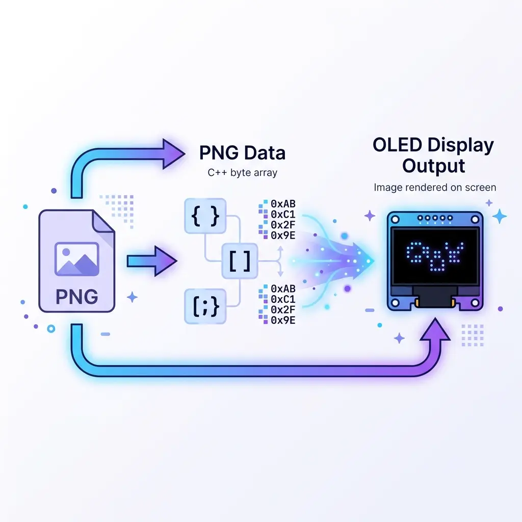
If you've ever tried to put a custom logo or image on an Arduino OLED display, you've probably run into this question: "How do I
turn my PNG file into something Arduino understands?" The answer is converting your image to a byte array—a long
list of numbers that represents your image pixel by pixel. I remember being totally baffled by this the first time. The code
examples showed these huge blocks of hex numbers like 0xFF, 0x81, 0x42... and I had no clue where they came from.
Here's the thing: your Arduino can't read PNG, JPG, or GIF files directly. It has no file system, no image decoder, nothing like that. Instead, images have to be converted into a byte array stored in PROGMEM (flash memory) that your code can reference. Each byte in that array controls 8 pixels on your display. This guide explains exactly how that conversion works, the popular image2cpp tool, and when you'll want an alternative that handles animations too.
By the end, you'll understand not just how to convert images, but why the process works the way it does. That understanding will save you when things go wrong—like when your image shows up upside down, inverted, or scrambled (all mistakes I've made and will help you avoid).
What exactly is an "image to byte array" conversion?
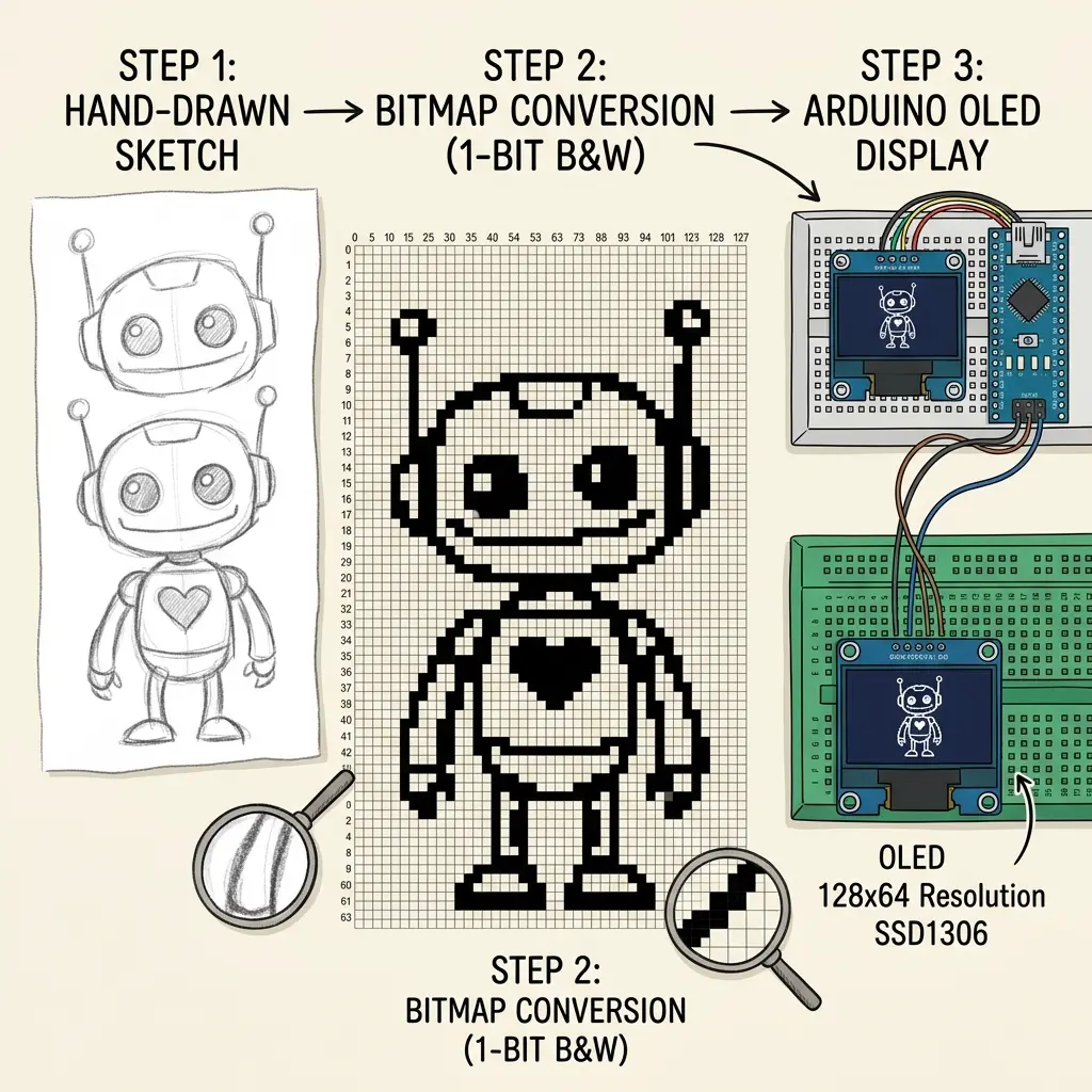
Let me explain this in the simplest way possible, because once it clicks, everything else makes sense.
Step 1: Your image becomes black and white
OLED displays like the SSD1306 are monochrome—each pixel is either ON (lit) or OFF (dark). There's no gray, no color. So the first thing that happens is your colorful image gets converted to pure black and white. A "threshold" value decides which pixels become white and which become black. Pixels brighter than the threshold turn on; darker ones turn off.
Step 2: Pixels get packed into bytes
Now here's the clever part. Instead of storing each pixel separately (wasteful), 8 pixels get packed into a single byte. A byte
is 8 bits, and each bit represents one pixel: 1 means "on," 0 means "off." So the byte 0b11110000 (or 0xF0
in hex) means "first four pixels on, last four pixels off."
For a 128×64 pixel display, you have 8,192 pixels total. Pack them 8 per byte, and you get exactly 1,024 bytes per image. That's why people say a full-screen 128×64 frame is "1KB." Now you know where that number comes from!
Step 3: The bytes become a C++ array
Finally, all those bytes get written out as a C++ array, like this:
const unsigned char myLogo[] PROGMEM = {
  0xFF, 0x81, 0x42, 0x24, 0x18, 0x18, 0x24, 0x42,
  // ... hundreds more bytes ...
};
The PROGMEM keyword tells Arduino to store this array in flash memory (where there's lots of room) instead of RAM
(where there's barely any). Then in your code, you display it with one line:
display.drawBitmap(0, 0, myLogo, 128, 64, WHITE);That's the whole magic. Image → black & white → packed bytes → C++ array → displayed with drawBitmap. Simple once you see it laid out.
image2cpp: the classic tool for single images
When it comes to converting one image to a byte array, image2cpp (created by javl, hugely popular on GitHub) is the tool everyone reaches for. And honestly, it's excellent at what it does. I've used it countless times for static logos and icons.
How to use image2cpp
- Upload your image: Drag a PNG, JPG, or BMP into the tool
- Set the canvas size: Match your display (usually 128×64)
- Adjust the threshold: Slide it until your image looks right in the preview—this controls which pixels are black vs white
- Pick the output format: Choose "Arduino code, single bitmap" for Adafruit GFX
- Copy the generated array: Paste it into your sketch and you're done
For a logo on your project's splash screen, or a single weather icon, image2cpp is perfect. Quick, free, no nonsense.
Common image2cpp gotchas (learn from my mistakes)
- Image appears inverted: Toggle the "Invert image colors" checkbox. Sometimes your background and foreground swap.
- Wrong orientation: Make sure the "Draw mode" matches how your library reads bitmaps. Horizontal vs vertical byte ordering matters.
- Blurry or muddy result: Your source image had too many midtones. Increase contrast in an image editor first, or enable dithering.
- Array too big: You probably didn't resize the image to your display dimensions before converting.
When you need more than image2cpp (the animation problem)
Here's where image2cpp hits its limit. It's built for single images. But what if you want an animation? Say you have a 15-frame loading spinner, or you want to convert an animated GIF. With image2cpp, you'd have to:
- Manually split your GIF into 15 separate PNG files
- Convert each one individually through image2cpp (15 times!)
- Copy-paste 15 arrays into your sketch
- Write the frame-cycling logic yourself
- Add timing code for the right FPS
- Debug it all when one array has the wrong size
I did this once for a 20-frame animation. It took me over an hour and I made two copy-paste errors that caused glitches. Never again. That experience is actually what led me to build a better tool.
What an animation-focused alternative gives you
- Multi-frame conversion – Import a whole GIF or PNG sequence at once, get all frames converted automatically
- Timeline with FPS control – Adjust playback speed visually and preview before exporting
- Multiple library targets – Export for Adafruit SSD1306, U8g2, or MicroPython framebuf
- Automatic SH1106 offset – No manual coordinate adjustments for SH1106 displays
- Complete project export – Get the full working sketch (arrays + playback loop), not just isolated arrays
- Built-in dithering – Floyd-Steinberg dithering for better-looking conversions of photos and gradients
Using the OLED Animation Maker as an image2cpp alternative
Here's how to convert images (single or animated) using the free OLED animation maker. The workflow handles both static images and full animations:
- Import tab: Drop your PNG, JPG, or GIF. Every frame automatically converts to byte arrays.
- Adjust threshold and dithering: Fine-tune how the image converts to black and white, with a live preview.
- Draw tab (optional): Use the built-in pixel editor if you want to design from scratch or touch up imported frames.
- Animate tab: Arrange frames on a timeline, set your FPS, and preview the motion.
- Get the Code: Export the complete sketch—byte arrays plus the playback loop—ready to upload.
You get the same core output as image2cpp (PROGMEM byte arrays), but with the animation workflow built in and your choice of library. For single images, it works just like image2cpp. For animations, it saves you that hour of tedious manual work.
Image → byte array + animation loop
Free online — SSD1306, SH1106, ESP32, Pico. Want pixels to assemble into a name or logo? Try OLED Name Assemble.
Open Tool →Popular searches: image to byte array arduino · image2cpp alternative · png to oled arduino · oled bitmap generator · progmem bitmap · custom image oled arduino
Frequently asked questions
What is the difference between a byte array and a bitmap?
They're basically the same thing in this context. A "bitmap" is an image made of pixels, and a "byte array" is how that bitmap is stored in code—as a list of bytes where each bit represents one pixel. When people say "convert image to byte array," they mean turning a picture into this code-friendly format.
Why use PROGMEM for image arrays?
Arduino has very little RAM (only 2KB on Uno). A single 128×64 image needs 1KB—half your RAM! PROGMEM stores the array in flash memory instead (32KB on Uno), freeing up RAM for your actual program. Always use PROGMEM for image data.
My image shows up inverted (black and white swapped). How do I fix it?
This is super common. Either toggle the "invert" option in your conversion tool, or change the color parameter in drawBitmap from WHITE to BLACK (or vice versa). It's a one-click fix once you know where to look.
Can I convert a color image, or does it have to be black and white?
You can start with any color image. The conversion tool automatically converts it to black and white using a threshold (and optionally dithering for better results). Just keep in mind the final display is monochrome, so high-contrast images work best.
What's dithering and should I use it?
Dithering simulates shades of gray using patterns of black and white dots—like how newspapers print photos. Use it for photos and gradients where you want to preserve detail. Skip it for logos, text, and simple graphics where you want clean solid shapes.
Why is a 128×64 image always 1024 bytes?
128 times 64 is 8192 pixels. The OLED stores one bit per pixel, and there are 8 bits in a byte, so 8192 / 8 = 1024 bytes. A smaller icon is smaller: an 8×8 glyph is 8 bytes if you pack eight vertical pixels into each byte.
My logo is mirrored or sliced into horizontal bars. What setting is wrong?
Adafruit GFX drawBitmap reads horizontal bytes: each byte is eight pixels across a row, and the leftmost pixel is the high bit. A vertical page-mode array (one byte per column) paints stripes. In image2cpp, choose the horizontal 1-bit mode that matches Adafruit GFX, then convert again.
Can I store the array in RAM instead of PROGMEM?
On an Uno, no. The frame is 1024 bytes and SRAM is only 2048. Leave the array in PROGMEM and let drawBitmap read it with the library’s flash helpers. Copying the whole frame into a RAM buffer is what makes a sketch reboot as soon as the image draws.
Worked example: pack an 8×8 mark, then a full frame
A full-screen logo is easier to trust after you have packed one tiny glyph by hand. Adafruit GFX drawBitmap stores the picture in horizontal bytes. Each byte is eight pixels in a row, and the leftmost pixel is the most significant bit. An 8×8 mark is one byte per row, so eight bytes, not 64.
A hollow 8×8 box is a useful check. The top and bottom rows are every pixel on: 0xFF. Each middle row is only the left and right pixels on, which is 10000001 binary, or 0x81. If that box draws as vertical stripes, the array was built in column-page order and the library is reading it as rows.
// Horizontal, MSB = left pixel. An 8x8 outline.
const unsigned char mark[] PROGMEM = {
  0xFF,
  0x81, 0x81, 0x81, 0x81, 0x81, 0x81,
  0xFF
};
display.drawBitmap(60, 28, mark, 8, 8, SSD1306_WHITE);
That call draws an 8×8 bitmap whose top-left is (60, 28), so it sits near the middle of a 128×64 panel and cannot clip. Scale the same packing up: 128 pixels per row is 16 bytes, times 64 rows, which is 1024 bytes. image2cpp and the animation maker both emit that length when the canvas is 128×64 and the output is a single Adafruit bitmap. If the array you pasted is 512 bytes, the source was 128×32 or half the rows were dropped. If it is 1056 bytes, someone built a 132-column SH1106 buffer (132 × 64 / 8). A normal SSD1306 frame should not be 1056; the extra columns are the SH1106 offset story, not a denser image.
Upload check on hardware: Uno SDA A4, SCL A5, begin(..., 0x3C). ESP32 uses GPIO 21 and GPIO 22. ESP8266 NodeMCU uses D2 and D1. Draw the 8×8 mark first. If those eight bytes look like noise, the byte order is wrong and a 1024-byte logo will look like noise too. Fix the mode, then convert the real PNG.
For a photograph, raise contrast before the threshold, or turn dithering on. For a wordmark, leave dithering off so edges stay solid. Invert only if the panel shows a white rectangle with a black logo and you wanted the opposite. PROGMEM stays on the array either way.
Troubleshooting a scrambled byte array
- Stripes every eight pixels. A column-packed (vertical) array was drawn with Adafruit’s horizontal
drawBitmap. Re-export as horizontal 1-bit, leftmost pixel in the high bit. - Image upside down. The tool’s “flip” or a library rotation setting. Do not hand-reverse 1024 hex values. Toggle the option and convert once.
- Right side clipped, left side has a two-pixel gap. The panel is SH1106 and the bitmap starts at column 0 of a 132-wide controller. Export with SH1106 selected, or pass x = 2 only if the driver does not already offset.
- Sketch uploads, then the board resets on drawBitmap. The array is in RAM. Add PROGMEM, and do not
memcpythe frame into a 1024-byte SRAM buffer on an Uno. - Logo is tiny in the corner. Width and height arguments still say 8, 8 from the test glyph. A full frame needs
drawBitmap(0, 0, logo, 128, 64, SSD1306_WHITE). - Colors swapped. Invert in the converter, or swap
SSD1306_WHITEandSSD1306_BLACKon a cleared black background. One of those, not both, or you invert twice and land back where you started.