Arduino OLED Blank Screen Fix — Checklist That Actually Works
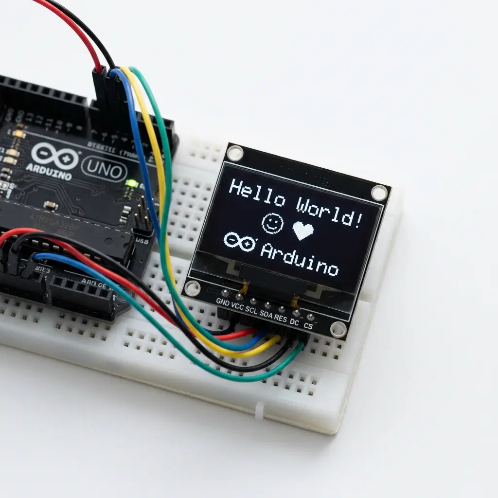
If I had a rupee for every “my OLED is dead” message, I could buy another crate of 0.96" modules. Most of them are not dead. In the lab, blank screens almost always fall into the same five buckets. Work through this list in order — do not skip to rewriting the whole sketch.
Fast checklist
- Power + GND solid? (measure VCC on the module pins)
- SDA/SCL on the correct pins for your board?
- I2C scanner finds
0x3Cor0x3D? - Sketch address matches the scanner?
- Did you call
display.display()after drawing? - Still garbage/shifted? Maybe SH1106, not SSD1306
1. Power problems look like “dead OLED”
Cheap modules are labeled 3.3–5V, but some clones are picky. On Uno, try 5V first. On ESP32, use 3.3V — do not feed 5V into a 3.3V-only board’s GPIO side carelessly.
Check with a multimeter between module VCC and GND while the Arduino is powered. 0V means a bad jumper or breadboard rail. Also reseat Dupont wires — half of “broken” displays in class are a wire that looks plugged in but isn’t.
2. SDA and SCL swapped or wrong pins
| Board | SDA | SCL |
|---|---|---|
| Uno / Nano (AVR) | A4 | A5 |
| Mega 2560 | 20 | 21 |
| Leonardo | 2 | 3 |
| ESP32 (common defaults) | 21 | 22 |
| ESP8266 (NodeMCU) | D2 (GPIO4) | D1 (GPIO5) |
If you swapped SDA and SCL, the scanner finds nothing. Swap them back before changing code.
3. Run the I2C scanner (do this before arguing with libraries)
#include <Wire.h>

void setup() {
  Wire.begin();
  Serial.begin(9600);
  while (!Serial) { ; }
  Serial.println(F("I2C scan"));
}

void loop() {
  byte n = 0;
  for (byte a = 1; a < 127; a++) {
    Wire.beginTransmission(a);
    if (Wire.endTransmission() == 0) {
      Serial.print(F("Found 0x"));
      if (a < 16) Serial.print('0');
      Serial.println(a, HEX);
      n++;
    }
  }
  if (!n) Serial.println(F("Nothing found"));
  delay(3000);
}
Found 0x3C or 0x3D: hardware link works. Fix the sketch address / init.
Nothing found: wiring or power. Libraries cannot help yet.
4. Wrong address in code
Adafruit examples sometimes default to 0x3D. Many Amazon modules are 0x3C.
Match whatever the scanner printed:
display.begin(SSD1306_SWITCHCAPVCC, 0x3C); // or 0x3D5. You drew pixels but never called display()
This one is embarrassing and extremely common. Adafruit draws into a RAM buffer. The panel stays black until:
display.clearDisplay();
display.setCursor(0, 0);
display.println(F("Hello"));
display.display(); // <-- without this, blank forever
6. “SSD1306 allocation failed”
begin() returned false. Usually means the bus address is wrong or the device never ACKs.
On Uno it can also mean you are out of SRAM (trying to allocate the 1 KB buffer failed). Check:
- Address matches scanner
- You are not creating two full 128×64 displays on a Uno without enough RAM
- Board selected in Tools → Board is correct
7. Image is there but shifted / wrapped
That is the classic SH1106 sold as SSD1306 problem. The picture looks like it slid two pixels sideways. Fix: use an SH1106-capable library/init, or buy a true SSD1306. Details: SH1106 vs SSD1306.
8. Works once, then freezes / flickers
- Calling
display()every millisecond with heavy drawing — slow down. - Long jumper wires on a noisy bench — shorten cables, common GND.
- Power dips when motors/servos share the same 5V rail — separate supply for motors.
9. Bad Dupont wires and cold solder joints
Module pins that barely grip breadboard rows create intermittent ACKs. Wiggle the four OLED wires while the scanner runs. If devices appear and vanish, replace the cable set. Factory modules sometimes ship with cold solder on the header — a quick reflow on VCC/GND/SDA/SCL has rescued more “dead” panels than new code.
10. Logic level and 5V vs 3.3V confusion
Uno is 5V tolerant on I2C with most SSD1306 breakouts (they level-shift or tolerate 5V). ESP32 is 3.3V — do not feed a 5V-only rail into ESP32 GPIO. If you borrow a level shifter, confirm you did not leave SDA floating on the 3.3V side.
11. Reset pin tied wrong
Many I2C tutorials pass -1 for reset because the module hardwires RES. If your breakout
exposes RES and you accidentally clamp it low, the panel stays dark forever. Leave RES floating/high
per module silkscreen.
12. Library mix-ups (U8g2 constructor vs Adafruit begin)
Copy-pasting a U8g2 constructor into an Adafruit sketch (or the reverse) wastes hours. Pick one stack per project. For animation libraries trade-offs, read U8g2 vs Adafruit SSD1306.
Workshop triage order I actually use
- Meter VCC on the module
- Scanner
- Minimal “OK” sketch below
- Only then restore your animation / GIF code
Students who reverse that order “debug animation maths” for twenty minutes on an unpowered display.
Minimal “prove hardware works” sketch
If this fails after a good scanner result, focus on address and library install:
#include <Wire.h>
#include <Adafruit_GFX.h>
#include <Adafruit_SSD1306.h>

Adafruit_SSD1306 display(128, 64, &Wire, -1);

void setup() {
  Serial.begin(9600);
  if (!display.begin(SSD1306_SWITCHCAPVCC, 0x3C)) {
    Serial.println(F("begin failed"));
    for (;;);
  }
  display.clearDisplay();
  display.setTextSize(2);
  display.setTextColor(SSD1306_WHITE);
  display.setCursor(10, 24);
  display.print(F("OK"));
  display.display();
}

void loop() {}
Still stuck?
Try another known-good OLED on the same wires. If the second module works, the first module or its header solder is bad — happens more than sellers admit. If neither works, the Arduino’s I2C pins or USB power are the suspects.
Scanner finds 0x3C, glass stays black
This is the failure that eats a lab period. Serial Monitor prints Found 0x3C, so VCC, GND, SDA, and SCL are good enough for an ACK. The panel is still black. The bus is alive; the controller is not lighting pixels. Do not swap libraries yet. Run this order on the same wires.
- The scanner and your sketch are different programs. A hit at
0x3Cplusdisplay.begin(SSD1306_SWITCHCAPVCC, 0x3D)still fails. Many 4-pin modules answer at0x3C. Some 128×64 boards, and the Adafruit example default, use0x3D. Copy the scanner’s number intobegin. - Check the address jumper or 0Ω resistor on the back of the module. Silkscreen often prints
0x78or0x7A. Those are 8-bit write addresses. Arduino wants the 7-bit form:0x78is0x3C,0x7Ais0x3D. Passing0x78tobegin()never matches, even when the scanner just found0x3C. - Construct the object with reset
-1on a 4-pin I2C board:Adafruit_SSD1306 display(128, 64, &Wire, -1);. That last argument is a GPIO wired to RES. If you pass pin 4 and pin 4 is low, or you clip the module’s RES pad to GND, the chip can still ACK and never leave reset. The glass stays dark forever. - After
begin()returns true, force contrast. A value of0x00looks identical to a dead panel. Then push a full white rectangle so a bad cursor cannot hide the test.
#include <Wire.h>
#include <Adafruit_GFX.h>
#include <Adafruit_SSD1306.h>

// 4-pin I2C modules: reset is -1 (RES is tied on the PCB).
Adafruit_SSD1306 display(128, 64, &Wire, -1);

void setup() {
  Serial.begin(9600);
  // Uno/Nano: Wire.begin() uses A4/A5.
  // Mega: pins 20 and 21. ESP32: Wire.begin(21, 22) first.
  // ESP8266 NodeMCU: Wire.begin(D2, D1) first.
  if (!display.begin(SSD1306_SWITCHCAPVCC, 0x3C)) {
    Serial.println(F("begin failed"));
    for (;;);
  }
  display.ssd1306_command(SSD1306_SETCONTRAST);
  display.ssd1306_command(0xCF);
  display.clearDisplay();
  display.fillRect(0, 0, 128, 64, SSD1306_WHITE);
  display.display();
}

void loop() {}
If the rectangle lights, the earlier sketch never called display(), used contrast 0, or drew off-screen. If it stays black while begin() succeeds, the init sequence does not match the chip. A white field slid about two columns, or only a bright strip at the left edge, means the PCB is an SH1106. That controller is 132×64 internally and shows a column offset when you drive it with an SSD1306 constructor. Install Adafruit SH110X and construct Adafruit_SH1106G (or the U8g2 SH1106 constructor). The I2C address can still be 0x3C — the address does not identify the controller.
Pull-ups, a second chip, and breadboard rows
Hobby SSD1306 boards usually include I2C pull-ups, often 4.7k or 10k from SDA and SCL up to VCC. You do not add another pair “because I2C needs resistors” unless the listing says the board ships without them. A second OLED, an RTC, or a sensor with its own 4.7k puts those resistors in parallel. Two 4.7k pull-ups are about 2.4k. On a short Uno jumper that often still works. On a Mega with 20 cm leads, or an ESP8266, the edges slow down and the scanner flips between Found 0x3C and Nothing found.
Real symptom: the OLED scans only when the RTC is unplugged. Keep one pull-up pair on the bus. Lift the extra resistors, or use a module that lets you disable them. Dropping the clock is the other practical test: Wire.setClock(100000); before begin() makes a marginal breadboard ACK at 100 kHz when 400 kHz fails. If 100 kHz is reliable and 400 kHz is not, shorten the wires instead of rewriting the sketch.
Breadboard contact copies the same symptom. The header pin sits in row 30 and the Dupont plug sits in row 31, or the plastic body stops the pin from seating. Wiggle SDA while the scanner loops every three seconds. If 0x3C appears and vanishes, move the module to another section of the breadboard and replace all four jumpers. A cold joint on the module header does this too — reflow VCC, GND, SDA, and SCL before you call the panel dead.
Two devices at the same address also look blank. Both ACK, so the scanner prints a single 0x3C, and neither finishes init cleanly. Unplug one board. If the remaining panel wakes up, you have a duplicate address. Move one module’s address resistor or solder jumper to 0x3D, or put a mux between them. Two full 128×64 Adafruit objects are also 2 KB of SRAM; on an Uno the second begin() can print allocation failed even when both panels are wired correctly.
5V Uno versus 3.3V boards
Uno and Nano: module VCC to 5V, SDA to A4, SCL to A5. Most SSD1306 breakouts tolerate that, and their onboard pull-ups then sit at 5V, which matches Uno GPIO. Mega 2560 uses the same 5V rail but I2C is pins 20 and 21, not A4/A5. A breadboard that worked on Uno goes black on Mega until those two jumpers move. The sketch text does not have to change on AVR, because Wire.begin() picks the hardware pins for the board you selected — if Tools → Board is still Uno while a Mega is plugged in, you are debugging the wrong pin map.
ESP32 defaults are GPIO21 (SDA) and GPIO22 (SCL), and the module must be powered from 3.3V. If you feed the OLED from the ESP32 5V pin while SDA and SCL go straight to GPIO, the module pull-ups rise to 5V and pull the ESP32 pins above 3.3V. Power the display from 3.3V so the resistors and the GPIO agree. Call Wire.begin(21, 22) before display.begin if you are not on the default pair.
ESP8266 NodeMCU silk is D2 (GPIO4, SDA) and D1 (GPIO5, SCL), VCC from the 3.3V pin. A Uno sketch that only calls Wire.begin() with no arguments talks on the wrong pins and the scanner reports nothing. Contrast is worth a second look on 3.3V: a sagging rail plus contrast left at a low value looks gray or fully black even though the scanner still finds the chip. The white-rectangle sketch above, with contrast 0xCF, separates “dim” from “not initialized.”
Bench symptoms and the matching fix
| What you see | Likely cause | Change this |
|---|---|---|
| Scanner: nothing | No VCC, swapped SDA/SCL, wrong board pins, open breadboard row | Meter module VCC, swap the data lines, match the pin table |
| Scanner: 0x3C, glass black | Sketch uses 0x3D or 0x78, RES held low, contrast 0, no display() | 7-bit address, reset -1, contrast 0xCF, push the buffer |
| Barely visible gray | Contrast command near 0, or a 3.3V rail sagging | SSD1306_SETCONTRAST then 0xCF; shorten power leads |
| Picture slid ~2 columns | SH1106 panel, SSD1306 constructor | SH1106 init; the RAM is 132 columns with an offset |
| Dies when a second module is plugged in | Same address, or pull-ups in parallel | One device per address; one pull-up pair |
| ACK blinks while you touch the wires | Dupont not seated, or a cold header joint | New jumpers, different breadboard rows, reflow the four pins |
I keep a copy of the white-rectangle sketch on the classroom laptop and I do not let students paste animation code until that rectangle is solid. If a second known-good OLED also stays black on those same four wires, the Arduino I2C pins or the USB 5V rail are the suspects, not the bitmap.
FAQ
The scanner finds 0x3C but the OLED stays black. Is the glass dead?
Usually no. Put that exact address in begin(), construct the display with reset -1 unless RES is really wired to a GPIO, send contrast 0xCF, draw a full white rectangle, and call display(). If the rectangle is shifted by about two columns, switch from an SSD1306 constructor to SH1106.
The board is printed 0x78. Why does begin(0x78) fail?
0x78 is the 8-bit write address. Shift it right by one bit and you get 0x3C, which is what Wire and Adafruit expect. The rear resistor or solder blob selects 0x78 versus 0x7A (0x3C versus 0x3D). It does not mean you should pass 0x78 to begin().
Do I add 4.7k resistors on SDA and SCL?
Only if the module documentation says pull-ups are not fitted. A normal 0.96" breakout already has them. A second board with its own 4.7k makes the bus stiffer and can turn a long cable into intermittent ACKs. Remove one pair instead of adding a third.
Same sketch, black screen after I moved from Uno to Mega or ESP32?
Uno and Nano use A4 and A5 at 5V. Mega uses pins 20 and 21. ESP32 uses GPIO21 and GPIO22 with the OLED on 3.3V, and ESP8266 NodeMCU uses D2 and D1. On Espressif boards call Wire.begin(SDA, SCL) before display.begin. Also confirm Tools → Board matches the PCB on the desk.
Related
When the screen works — try an animation
Use the free maker to export Adafruit code once Hello World is solid.
Open oledanimationmaker.com →