Dual OLED Arduino — Two SSD1306 Displays on One I2C Bus
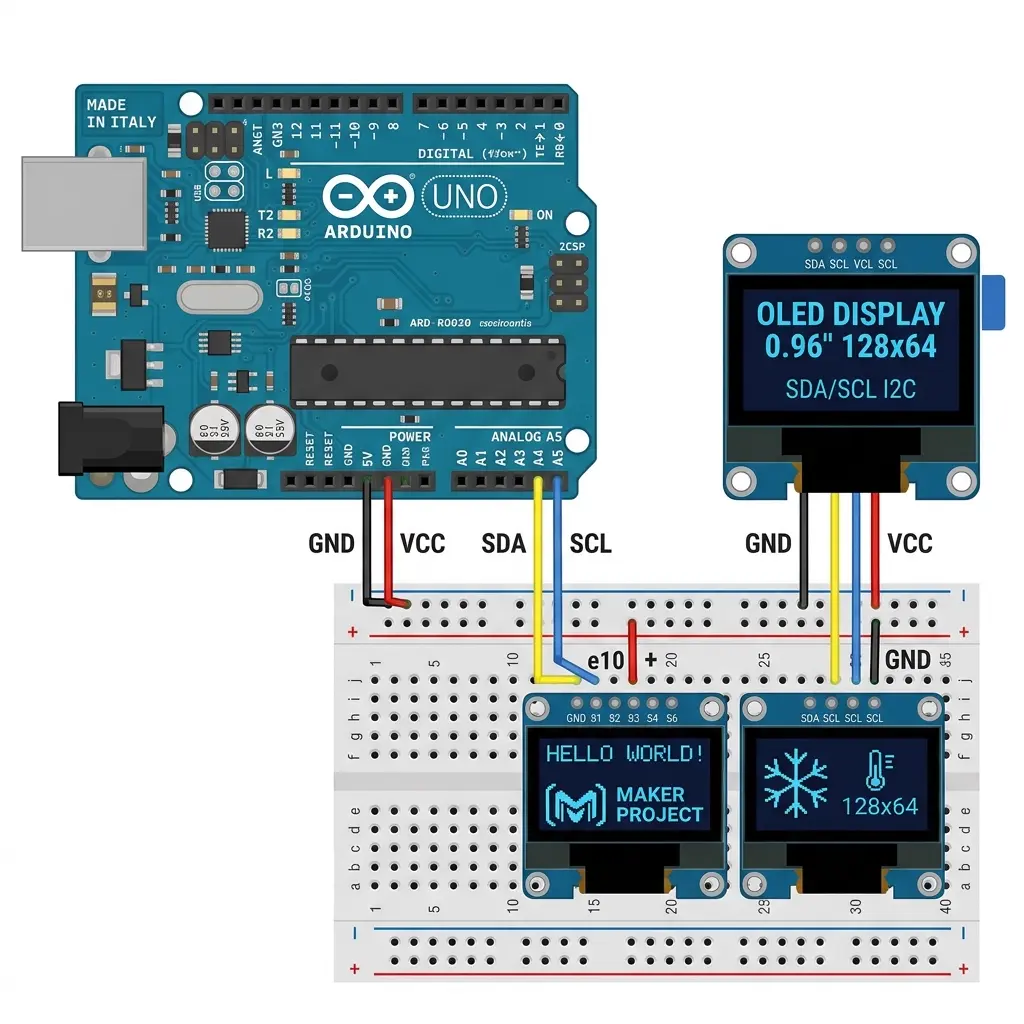
Students ask for this constantly: “Can I run two OLEDs from one Arduino?” Yes — if the
modules can use different I2C addresses. Most cheap 0.96" boards ship as
0x3C. For two screens on the same SDA/SCL wires, one of them must become 0x3D.
If both stay on 0x3C, the bus fights itself. You will see flicker, wrong content, or only one
panel responding. That is not a library bug — it is an address collision.
What you need
- Arduino Uno / Nano (or ESP32 — same idea, different SDA/SCL pins)
- Two I2C SSD1306 modules (4-pin: VCC GND SDA SCL)
- At least one module with an address select pad / resistor / jumper for
0x3D - Adafruit GFX + Adafruit SSD1306 libraries
Hardware: change one display to 0x3D
Look on the back of the PCB. Many boards have a tiny solder jumper labeled ADDR, 0x3C / 0x3D, or a resistor footprint next to the controller. Closing the jumper (or moving the 0Ω resistor) switches the address.
Not every AliExpress module has this. If both boards are hard-wired to 0x3C with no pad, you
cannot put them on the same I2C bus without a multiplexer (TCA9548A). Buy modules that document dual-address
support, or use SPI OLEDs with separate CS pins instead.
Wiring (shared bus)
| Both OLEDs | Arduino Uno / Nano |
|---|---|
| VCC | 5V (check 3.3V-only modules) |
| GND | GND |
| SDA | A4 (shared) |
| SCL | A5 (shared) |
Same four nets for both panels. Power both from the board if current is modest; for long cables use a solid GND and consider a 0.1 µF cap near each module if you see sparkles.
Verify with the I2C scanner
Before writing dual-screen code, upload a scanner. You want two lines:
I2C device found at 0x3C
I2C device found at 0x3D
Only one address? The second module did not switch, or a wire is loose. Fix hardware first.
Working sketch: two Adafruit_SSD1306 objects
Important: each display object has its own 1 KB buffer on Uno. Two 128×64 buffers ≈ 2 KB — that is basically all of Uno SRAM. Keep other globals tiny, or use 128×32 panels / ESP32.
#include <Wire.h>
#include <Adafruit_GFX.h>
#include <Adafruit_SSD1306.h>

#define W 128
#define H 64

Adafruit_SSD1306 displayA(W, H, &Wire, -1); // 0x3C
Adafruit_SSD1306 displayB(W, H, &Wire, -1); // 0x3D

void setup() {
  Serial.begin(9600);

  if (!displayA.begin(SSD1306_SWITCHCAPVCC, 0x3C)) {
    Serial.println(F("Display A (0x3C) failed"));
    for (;;);
  }
  if (!displayB.begin(SSD1306_SWITCHCAPVCC, 0x3D)) {
    Serial.println(F("Display B (0x3D) failed"));
    for (;;);
  }

  displayA.clearDisplay();
  displayA.setTextSize(2);
  displayA.setTextColor(SSD1306_WHITE);
  displayA.setCursor(0, 20);
  displayA.println(F("Screen A"));
  displayA.display();

  displayB.clearDisplay();
  displayB.setTextSize(2);
  displayB.setTextColor(SSD1306_WHITE);
  displayB.setCursor(0, 20);
  displayB.println(F("Screen B"));
  displayB.display();
}

void loop() {
  // Example: bounce a marker on A, counter on B
  static int x = 0;
  static int dir = 1;

  displayA.clearDisplay();
  displayA.fillCircle(x, 32, 6, SSD1306_WHITE);
  displayA.display();

  displayB.clearDisplay();
  displayB.setTextSize(2);
  displayB.setCursor(0, 24);
  displayB.print(F("x="));
  displayB.print(x);
  displayB.display();

  x += dir;
  if (x < 6 || x > 121) dir = -dir;
  delay(30);
}
Mistakes I see every time
- Calling begin() twice with 0x3C. Second display must be
0x3D. - Updating only one object.
displayA.display()does not refresh B. - SRAM exhaustion on Uno. Two full buffers + big bitmaps = random crashes. Drop resolution or move to ESP32.
- Mixing SH1106 and SSD1306 without the right drivers — one panel will look shifted.
When you need more than two
Three+ devices on the same address space need a TCA9548A I2C multiplexer, or SPI displays with separate chip-select lines. For classroom demos, two I2C panels at 0x3C/0x3D is the sweet spot.
Classroom project ideas with two screens
- Conversation bots — face A talks (mouth frames), face B reacts. See robot eyes and put one eye or face per panel.
- Split dashboard — temperature on A, humidity bar on B from the weather station guide.
- Menu + preview — navigation list on A, live gauge on B using the menu and dashboard patterns.
Dual screen doubles SRAM cost on Uno. If students hit random reboots after adding bitmaps, move the demo to ESP32 or drop to 128×32 panels — explained in Uno memory limits.
Using Dual Screen mode in the tool
In OLED Animation Maker, choose Dual Screen (2 OLEDs) if you want different animations on A and B. The exporter targets the same 0x3C / 0x3D pattern as this sketch.
FAQ
Can both displays show the same animation?
Yes — draw into both buffers the same way, or draw once and copy commands. Usually people want different content though.
Do I need pull-up resistors?
Most modules already have I2C pull-ups. Two modules = two sets of pull-ups, which is usually still OK. If the bus is flaky with long wires, check voltage levels with a meter.
Uno vs ESP32 for dual OLED?
ESP32 has far more RAM. Dual 128×64 is uncomfortable on Uno; fine on ESP32.
Set the second address before you share the wires
Two SSD1306 modules on one bus only work when one answers at 0x3C and the
other at 0x3D. Out of the bag, most 0.96" boards answer at
0x3C. Putting both on A4 and A5 in that state does not give you a mirrored
pair. The controllers talk over each other, and you get a blank panel, a flicker, or
one screen that updates while the other ignores you. Fix the address on the bench,
with one module connected, before you tie the second module in.
On the back, look for a solder jumper marked ADDR, 0x78 / 0x7A
(those are the 8-bit write addresses for 0x3C and 0x3D), or a 0Ω resistor you can move.
Close the jumper on one board only. Leave the other board at the factory
setting. Power that modified board by itself and confirm a scanner prints
0x3D. Then connect the untouched board and confirm both lines. If you
close the jumper on both, you have simply moved the collision from 0x3C to 0x3D.
Some modules have no pad. No amount of begin() calls will invent a second
address. Those boards need a TCA9548A multiplexer, or you switch to SPI panels with
separate chip-select pins. I keep a labeled pair in the parts box — one with a dab of
paint on the 0x3D jumper — because hunting for the right module mid-class wastes the
hour.
ESP32 and ESP8266 pins for the same two modules
The shared-bus table above is the Uno/Nano map: SDA on A4, SCL on A5, VCC on 5V if the module has a regulator. The ESP boards use different pins and a different rail.
- ESP32: both OLEDs share SDA on GPIO21 and SCL on GPIO22. Power both from 3.3V. ESP32 I/O is not a 5V I2C bus. A module that “worked on Uno 5V” still belongs on 3.3V here.
- ESP8266 NodeMCU: both OLEDs share SDA on D2 (GPIO4) and SCL on D1 (GPIO5), VCC on 3.3V. If
begin()fails on both addresses, callWire.begin(4, 5)before either display starts. One begin for the bus, then twodisplay.begin()calls with 0x3C and 0x3D. - Do not split the bus by wiring screen A to the default pins and screen B to a random pair. Both controllers must see the same SDA and the same SCL. Separate chip selects are an SPI idea. I2C separates devices by address.
GND is one net. Run a ground wire to each module from the board, not a daisy chain of three thin jumpers if you can avoid it. Dual panels draw their pixel current together when both buffers push a full white frame. A lazy ground shows up as speckle on both glasses at once.
Two 128×64 buffers and the Uno’s 2 KB
Each Adafruit_SSD1306 object for 128×64 keeps a 1024-byte SRAM buffer.
Two of them are 2048 bytes. An Uno’s SRAM is 2048 bytes, and the core, stack, and
millis() already need a slice. This is why the sketch above can print
“Screen A” / “Screen B” and bounce a circle, and why it falls over when a student
pastes a full-screen bitmap into ordinary RAM beside those objects.
The failure is a reset loop, not a polite error. Flash can still look fine in the IDE (“sketch uses 18 KB”) while SRAM is reported near 100 percent. Read the second line of the compile summary, the global-variables line, before you celebrate. If dynamic memory is much past about 1500 bytes on Uno, stop adding features.
Ways that actually fit:
- Keep both panels at 128×64 only on an ESP32, which has RAM to spare for two buffers.
- Use 128×32 modules. Each buffer drops to 512 bytes, so two of them are 1 KB and an Uno can breathe.
- Store animation frames in
PROGMEM(flash), and draw them into the existing buffers. Flash holds the pictures. SRAM only holds the two live frames.
A long clip does not become dual-screen friendly just because you have two panels. One 128×64 frame is 1 KB of flash. A 150-frame loop is about 150 KB. A 200-frame loop is about 200 KB. Uno flash is about 32 KB, so those loops belong on an ESP32 or a 4MB ESP8266 whether you own one OLED or two. Dual display doubles SRAM traffic. It does not double flash in a useful way if you show the same frames on both sides — and it does double flash if you store a different 200-frame clip per panel.
Draw one PROGMEM clip to both panels
When screen A and screen B should play the same short loop, keep a single frame table
in flash and pass each pointer to both objects. You pay 1024 bytes of flash per frame
once, and you pay 1024 bytes of SRAM per panel. The loop shape matches the other
Adafruit players on this site, with two display() calls so each controller
gets its own I2C payload.
void loop() {
  static uint8_t frameIdx = 0;
  static unsigned long lastMs = 0;
  const uint8_t* frames[] = { frame0, frame1, frame2 };
  const uint8_t numFrames = 3;

  if (millis() - lastMs >= 100) {
    lastMs = millis();
    const uint8_t* f = frames[frameIdx];

    displayA.clearDisplay();
    displayA.drawBitmap(0, 0, f, 128, 64, SSD1306_WHITE);
    displayA.display();

    displayB.clearDisplay();
    displayB.drawBitmap(0, 0, f, 128, 64, SSD1306_WHITE);
    displayB.display();

    frameIdx = (frameIdx + 1) % numFrames;
  }
}
On AVR, if the pointer table itself is PROGMEM, read the pointer with
pgm_read_word the way the Uno memory article shows. Forgetting that makes
both panels show the same garbage, which people misread as an address clash. If only
one panel is garbage, the addresses are crossed or one drawBitmap is
using the wrong object.
I2C is half-duplex and this bus is shared, so the transfers happen one after another.
Two full frames at 100 kHz are on the order of 180 ms of wire time. The earlier circle demo uses delay(30), which is fine because a circle is a few bytes of
commands, not a 1024-byte bitmap. Do not expect two full-frame animations to hit 15 fps
combined. Budget a delay of at least 100 ms per step, or call
Wire.setClock(400000) after Wire.begin() and measure again.
Screen B will always update a moment after screen A. That stagger is the bus, not a
missed begin().
Power, pull-ups, and how long the cable can be
Each module usually has its own I2C pull-ups to its VCC. Two modules mean two pairs in parallel, which is still fine at the desk. A third device on the same bus, plus a long cable, is where edges get round and the scanner becomes intermittent. If a scanner sometimes sees only 0x3C, shorten the leads before you add external resistors. Extra pull-ups on top of two module pairs can be too strong.
Power both panels from the same rail the logic uses. On Uno, 5V and GND from the
Arduino, if you have checked that the modules regulate down to the controller. On ESP
boards, 3.3V and GND. Mixing one module on 5V and one on 3.3V on the same SDA/SCL pair
is a good way to stress a pin. A 0.1 µF capacitor from VCC to GND at each module, close
to the pins, calms sparkle when both display() calls land back to back.
Leave RST unwired when you construct the object with -1, which is what the
sketch above does. If your module has a reset pin and you wire it to a GPIO, pass that
pin into the constructor for that object only. Tying both RST pins to one GPIO
is fine if you want them to reset together. Leaving one RST floating on a board that
requires it looks like a single dead panel while the other works.
A scanner you can paste before the dual sketch
Upload this, open Serial at 9600, and do not start the Adafruit sketch until you see
two addresses. On ESP32 the same scan works if you call Wire.begin(21, 22).
On NodeMCU use Wire.begin(4, 5).
#include <Wire.h>

void setup() {
  Wire.begin(); // Uno/Nano: SDA A4, SCL A5
  Serial.begin(9600);
  for (byte addr = 1; addr < 127; addr++) {
    Wire.beginTransmission(addr);
    if (Wire.endTransmission() == 0) {
      Serial.print(F("I2C device found at 0x"));
      if (addr < 16) Serial.print('0');
      Serial.println(addr, HEX);
    }
  }
}

void loop() {}
Zero devices: power or SDA/SCL swapped. One device: the second module is unpowered,
unwired, or still at the same address as the first. 0x3C and
0x3D together: you are allowed to open the dual sketch. Any other pair
(a sensor at 0x48 plus one OLED, for example) means you must not reuse that sensor’s
address, but the two OLEDs are still the ones that must be 0x3C and 0x3D.
What fails when both panels are in the sketch
- Only A works. B is still at 0x3C, or
displayB.beginwas given 0x3C by copy-paste. The scanner is the proof. - Both show the same text when they should differ. You drew into one object and called
display()on both, or you called onlydisplayA.display(). Each object needs its own draw and its owndisplay(). - Uno resets when the animation starts. SRAM. Two full buffers plus a RAM bitmap. Move frames to PROGMEM or move the demo to ESP32.
- IDE board mismatch. A dual sketch compiled for Uno uses A4/A5 and the AVR Wire core. Uploaded to an ESP32, it never runs, and both panels stay dark. Pick the board that matches the USB chip, then the port.
- Not enough flash once you add a long loop. The text demo is small. A 150 or 200 frame clip is 150–200 KB and will not fit an Uno even for a single panel. Dual Screen in the maker does not raise that ceiling. It only emits two addresses.
- One panel is shifted by a few columns. That panel is often an SH1106 sold as an SSD1306. The other can be a real SSD1306. They need matching drivers, or the shifted one needs the SH1106 constructor. Mixing them on one bus is electrically fine and visually wrong.
Using the maker’s dual export without fighting this wiring
Dual Screen mode in the tool is the same pair this article uses: one animation for address 0x3C, another for 0x3D. Design the two timelines only after the scanner shows both addresses. If you export first and wire later, you will debug the art when the jumper was never closed. Keep each timeline short on Uno. On ESP32 you can give each side a longer loop, remembering that different clips cost flash twice and that the shared bus plays them one transfer after the other.
A classroom order that works: scanner, then the “Screen A / Screen B” text sketch, then a three-frame PROGMEM loop drawn to both objects, then a split (menu on A, preview on B). Students who jump straight to two full video imports spend the period on “sketch too big” and never see two addresses work.
Related
Design Screen A and Screen B separately
Dual Screen mode → export code for both addresses.
Open the tool →