ESP-NOW OLED display: send data between two ESP32 boards
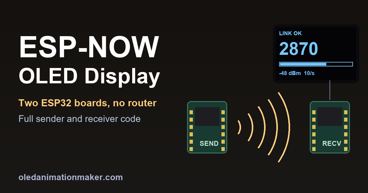
An ESP-NOW OLED display is a great way to learn wireless projects. Two ESP32 boards talk to each other directly, with no WiFi router, no internet and no phone app. One board sends a number, and the other shows it on a small SSD1306 screen. This guide builds exactly that, with full code for both boards, a signal strength readout, and fixes for the problems that usually stop it from working.
An ESP-NOW relay guide with OLED feedback was among this month's ESP32 project coverage. The usual tutorial shows two bare sketches and a Serial Monitor. Here you get a proper receiver screen with a live value, a bar, signal strength in dBm, packets per second and a "no signal" warning, so you can see the link working.
Quick answer. Flash the sender sketch to one ESP32 and the receiver sketch to the other. The sender reads a knob and broadcasts it ten times a second with esp_now_send(). The receiver catches each packet in a callback and draws the value on the OLED. You need the ESP32 Arduino core version 3 or newer, because the receive callback changed in that version.
What ESP-NOW is, and when to use it
ESP-NOW is a protocol from Espressif, the company that makes the ESP32. It lets ESP boards send small packets straight to each other using the WiFi radio. There is no router in the middle and no connection to set up. A packet can hold up to 250 bytes, which is plenty for a few sensor readings.
It is a good fit when you want a remote sensor, a wireless button, a remote display or a cordless switch, and the boards sit within a room or a house of each other. It is not a good fit if you need the internet, or if you need to talk to a phone or a computer. For those, use normal WiFi, as in the wireless WiFi OLED live preview guide.
What you will build
The sender is an ESP32 with a potentiometer, which is a knob that gives a number from 0 to 4095. The receiver is an ESP32 with an SSD1306 OLED. Turn the knob and the receiver shows the number in big digits, with a bar that fills across the screen. It also shows the signal strength of the last packet. Two more numbers show how many packets arrive each second and how many were lost.
If the sender is switched off, the receiver shows "NO SIGNAL" after one second. That makes it easy to see when a battery has died or a board is out of range.
What you need
- Two ESP32 boards. Two DevKit V1 boards cost roughly $12 to $20 together on Amazon US. ESP32-C3 and ESP32-S3 boards work too.
- A 0.96 inch 128x64 I2C OLED with the SSD1306 chip, about $5 to $8. It goes on the receiver.
- A 10k potentiometer for the sender, about $1 to $3. Any knob from 1k to 100k works.
- Jumper wires and two USB cables.
Wire the sender and the receiver
The two boards are not connected by wires. Each one gets its own USB power. Wire the knob to the sender and the screen to the receiver, using these tables.
| Board | Part pin | Connect to |
|---|---|---|
| Sender | Potentiometer, one outer pin | 3V3 |
| Sender | Potentiometer, other outer pin | GND |
| Sender | Potentiometer, middle pin | GPIO 34 |
| Receiver | OLED GND | GND |
| Receiver | OLED VCC | 3V3 |
| Receiver | OLED SDA | GPIO 21 |
| Receiver | OLED SCL | GPIO 22 |
GPIO 34 is an input-only pin on the ESP32 that works with analogRead() while WiFi is on, which is why it is a safe choice. Read the labels on your OLED before you connect power, because some modules put VCC and GND in a different order. The ESP32 OLED wiring guide shows the same four OLED wires in more detail.
Install the ESP32 core and the OLED library
- In the Arduino IDE, open Tools > Board > Boards Manager, search for esp32 and install esp32 by Espressif Systems version 3.0 or newer.
- Pick ESP32 Dev Module as the board for each DevKit V1.
- Open Sketch > Include Library > Manage Libraries, search for Adafruit SSD1306 and install it. Accept the offer to install Adafruit GFX and Adafruit BusIO.
ESP-NOW itself needs no library. The esp_now.h header comes with the ESP32 core, and its functions are documented in the Espressif ESP-NOW reference. The screen code uses the Adafruit SSD1306 library.
The ESP-NOW sender code
Upload this to the board with the knob. It reads the knob, packs the value into a small packet and broadcasts it.
// ESP-NOW sender: reads a potentiometer and broadcasts it 10 times a second
// Needs the ESP32 Arduino core 3.x
#include <WiFi.h>
#include <esp_now.h>

const int POT_PIN = 34;   // CHANGE: any ADC1 pin (32 to 39) on a DevKit V1
const uint8_t BROADCAST[6] = {0xFF, 0xFF, 0xFF, 0xFF, 0xFF, 0xFF};  // every ESP32 in range

// Both sketches must use the same packet layout
struct __attribute__((packed)) Packet {
  uint8_t  magic;   // always 0xA5, so the receiver can ignore other ESP-NOW traffic
  uint16_t seq;     // counts up, so the receiver can spot lost packets
  uint16_t value;   // knob reading, 0 to 4095
};
Packet pkt = {0xA5, 0, 0};

void setup() {
  Serial.begin(115200);
  WiFi.mode(WIFI_STA);                       // ESP-NOW needs the WiFi radio on
  if (esp_now_init() != ESP_OK) {
    Serial.println("ESP-NOW init failed");
    while (true) delay(1000);
  }
  esp_now_peer_info_t peer = {};
  memcpy(peer.peer_addr, BROADCAST, 6);
  peer.channel = 0;                          // 0 = use the radio's current channel
  peer.encrypt = false;                      // broadcast cannot be encrypted
  if (esp_now_add_peer(&peer) != ESP_OK) {
    Serial.println("Could not add the broadcast peer");
    while (true) delay(1000);
  }
  Serial.println("Sender ready");
}

void loop() {
  uint32_t sum = 0;                          // average 8 reads to calm the ESP32's noisy ADC
  for (int i = 0; i < 8; i++) sum += analogRead(POT_PIN);
  pkt.value = sum / 8;
  pkt.seq++;

  esp_err_t result = esp_now_send(BROADCAST, (uint8_t *)&pkt, sizeof(pkt));
  if (result != ESP_OK) Serial.printf("Send error %d\n", (int)result);
  delay(100);                                // 10 packets per second
}
The ESP-NOW receiver code with the OLED
Upload this to the board with the screen. The callback only stores the numbers. All drawing happens in loop(), because the callback runs inside the WiFi task and should stay short.
// ESP-NOW receiver: shows the value, a bar, signal strength and link status on an SSD1306
// Needs the ESP32 Arduino core 3.x
#include <WiFi.h>
#include <esp_now.h>
#include <Wire.h>
#include <Adafruit_GFX.h>
#include <Adafruit_SSD1306.h>

const int SDA_PIN = 21;           // CHANGE: DevKit V1 = 21, C3 SuperMini = 8
const int SCL_PIN = 22;           // CHANGE: DevKit V1 = 22, C3 SuperMini = 9
const uint8_t OLED_ADDR = 0x3C;   // CHANGE to 0x3D if your screen needs it
Adafruit_SSD1306 display(128, 64, &Wire, -1);

struct __attribute__((packed)) Packet {   // same layout as the sender
  uint8_t  magic;
  uint16_t seq;
  uint16_t value;
};

// Written by the callback, read by loop()
volatile uint16_t lastValue = 0;
volatile int      lastRssi = -100;
volatile uint32_t lastRxMs = 0;
volatile uint32_t rxCount = 0;
volatile uint32_t lostCount = 0;
volatile uint16_t lastSeq = 0;
volatile bool     haveSeq = false;

// Core 3.x callback: the first argument carries the sender's MAC and the signal strength
void onReceive(const esp_now_recv_info_t *info, const uint8_t *data, int len) {
  if (len != (int)sizeof(Packet)) return;     // wrong size: not ours
  Packet p;
  memcpy(&p, data, sizeof(p));
  if (p.magic != 0xA5) return;                // wrong magic byte: not ours
  if (haveSeq) {
    uint16_t gap = (uint16_t)(p.seq - lastSeq - 1);   // packets missed since the last one
    if (gap < 1000) lostCount = lostCount + gap;      // a huge gap means the sender restarted
  }
  haveSeq = true;
  lastSeq = p.seq;
  lastValue = p.value;
  lastRssi = info->rx_ctrl->rssi;
  lastRxMs = millis();
  rxCount = rxCount + 1;
}

void drawScreen(uint32_t pps) {
  bool linked = rxCount > 0 && (millis() - lastRxMs) < 1000;
  display.clearDisplay();
  display.setTextColor(SSD1306_WHITE);
  display.setTextSize(1);
  display.setCursor(0, 0);
  display.print(linked ? "ESP-NOW  LINK OK" : "ESP-NOW  NO SIGNAL");
  if (linked) {
    display.setTextSize(3);
    display.setCursor(0, 14);
    display.print((int)lastValue);                          // big number, 0 to 4095
    display.drawRect(0, 42, 128, 10, SSD1306_WHITE);        // bar outline
    int w = map((int)lastValue, 0, 4095, 0, 124);
    display.fillRect(2, 44, w, 6, SSD1306_WHITE);           // bar fill
    display.setTextSize(1);
    display.setCursor(0, 56);
    display.printf("%d dBm  %u/s  lost %u", (int)lastRssi, (unsigned)pps, (unsigned)lostCount);
  } else {
    display.setCursor(0, 24);
    display.print("Is the sender on?");
  }
  display.display();
}

void setup() {
  Serial.begin(115200);
  Wire.setPins(SDA_PIN, SCL_PIN);
  if (!display.begin(SSD1306_SWITCHCAPVCC, OLED_ADDR)) {
    Serial.println("OLED not found: check wiring and the address");
    while (true) delay(1000);
  }
  WiFi.mode(WIFI_STA);
  if (esp_now_init() != ESP_OK) {
    Serial.println("ESP-NOW init failed");
    while (true) delay(1000);
  }
  esp_now_register_recv_cb(onReceive);
  Serial.println("Receiver ready, MAC: " + WiFi.macAddress());
}

void loop() {
  static uint32_t lastDraw = 0, lastCount = 0, pps = 0, lastSecond = 0;
  if (millis() - lastSecond >= 1000) {         // packets per second
    lastSecond = millis();
    pps = rxCount - lastCount;
    lastCount = rxCount;
  }
  if (millis() - lastDraw >= 100) {            // redraw 10 times a second
    lastDraw = millis();
    drawScreen(pps);
  }
}
Power both boards. The receiver first shows "NO SIGNAL". A moment after the sender starts, it flips to "LINK OK" and the number follows the knob. At ten packets per second you should see about 10/s, and the lost counter should stay near zero.
I checked these sketches against Espressif's esp_now.h header for the function names and the receive callback. I could not run two boards while writing this page, so treat the troubleshooting list below as part of the project.
How the two sketches work
- Turn the WiFi radio on.
WiFi.mode(WIFI_STA)starts the radio without joining any network. ESP-NOW rides on it. - Start ESP-NOW.
esp_now_init()sets it up. It returnsESP_OKwhen it worked. - Add the destination. Every ESP-NOW destination must be added as a peer first. The sender adds the broadcast address, all
0xFF, which means "everyone in range". - Send a packet.
esp_now_send()sends the 5 byte struct. The sender never waits for an answer, so it keeps working even if nobody is listening. - Catch it. The receiver registers
onReceive()withesp_now_register_recv_cb(). The ESP32 calls it for every packet that arrives. - Check and store. The callback checks the size and the magic byte, counts gaps in the
seqcounter as lost packets, and saves the value and signal strength. - Draw.
loop()reads the saved numbers and redraws the screen ten times a second.
The seq counter is the trick that makes the "lost" number work. Each packet is one higher than the last, so a jump from 40 to 43 means two packets were missed. If the sender restarts, the counter drops back to zero, and the sketch ignores that jump.
Make the link private with the receiver's MAC address
Broadcast is the easiest way to start, but any ESP32 in range can hear it. The magic byte only filters out unrelated traffic. It is not security. For a private link, send to one board by its MAC address, which is a unique ID for each board's radio.
- Open the receiver's Serial Monitor at 115200 baud. The sketch prints "Receiver ready, MAC: " followed by six pairs of characters, such as
A4:CF:12:34:56:78. - In the sender, replace the
BROADCASTarray with those six bytes, written as0xA4, 0xCF, 0x12, 0x34, 0x56, 0x78. - For encryption, set
peer.encrypt = trueand fill inpeer.lmkwith a 16 byte key. Both boards need the same key setup, so read the Espressif reference before you rely on it.
Troubleshooting the ESP-NOW OLED display
- Problem: the receiver stays on "NO SIGNAL". Why: the boards are on different WiFi channels, or the sender is not running. Fix: check that the sender prints "Sender ready" and no "Send error". Make sure neither sketch connects to a router with
WiFi.begin(). - Problem: it worked, then stopped after I added WiFi code. Why: joining a router moves that board's radio to the router's channel, and the other board stays on channel 1. Fix: do not mix them, or set the same channel on both boards before you start ESP-NOW.
- Problem: a compile error about the callback. Why: you are using ESP32 core 2.x. Its receive callback starts with a plain MAC address instead of
esp_now_recv_info_t. Fix: update the board package to version 3 or newer. - Problem: "ESP-NOW init failed". Why: the WiFi radio was not turned on first. Fix: call
WiFi.mode(WIFI_STA)beforeesp_now_init(). - Problem: "Send error" numbers in the sender's Serial Monitor. Why: the peer was not added, or the WiFi radio is not ready. Fix: check that
esp_now_add_peer()succeeded, and callesp_now_send()only aftersetup()has finished. - Problem: the OLED stays black. Why: a wrong address, wrong pins, or swapped SDA and SCL. Fix: try 0x3D and check the wiring. The SSD1306 blank screen fixes include an I2C scanner.
- Problem: the value jumps around while the knob is still. Why: the ESP32's analog input is noisy. Fix: the sender already averages 8 reads. Add a 0.1 microfarad capacitor between the knob's middle pin and ground for a steadier number.
- Problem: many lost packets. Why: distance, thick walls, metal, or a board with a weak antenna. Fix: move the boards closer, move the receiver away from metal, and check the dBm number. A value near -90 dBm is weak.
Ideas to build on it
- A wireless weather display. Swap the knob for a DHT22 sensor on the sender and show temperature and humidity on the receiver. The Arduino OLED weather station guide has the sensor code.
- A better screen. Add gauges and animated bars to the receiver. The OLED dashboard guide has ready-made ones.
- A wireless button. Replace the knob with a push button and send a 1 or a 0 to switch an LED or a relay on the other board.
- An animated alert. Draw a warning icon in the OLED Animation Maker, export the frames, and play them when the link drops.
- Battery power. The sender can run from a battery. The OLED power consumption guide shows how to estimate the run time.
Next steps
- Test the receiver layout before you wire it, using the OLED simulator.
- Learn more drawing calls in the OLED shapes guide.
- Make a startup logo for the receiver with the Image to Byte Array tool.
Frequently asked questions
Do I need a WiFi router for ESP-NOW?
No. ESP-NOW sends data straight from one ESP32 to another using the WiFi radio, with no router, no internet and no password. Both boards only need to be powered and on the same channel.
How much data can one ESP-NOW packet carry?
Up to 250 bytes in one packet on a standard ESP32. That is plenty for a few sensor readings. The sketch on this page sends a 5 byte packet.
Why does ESP-NOW stop working when I add WiFi to the sketch?
Once a board joins a router, its radio moves to the router's channel. The other board is still on channel 1, so they can no longer hear each other. Put both boards on the same channel.
Can I use an ESP32-C3 or ESP32-S3 with ESP-NOW?
Yes. Any ESP32 with WiFi can use ESP-NOW. Change the OLED pins in the receiver sketch and the potentiometer pin in the sender sketch to pins your board has.
Is broadcast ESP-NOW private?
No. A broadcast can be heard by any ESP32 in range. For a private link, send to the receiver's MAC address and turn on encryption. The magic byte in the sketch only filters out other traffic, it is not security.
Related guides
- Wireless WiFi OLED live preview for Arduino
- ESP32 OLED animation: SSD1306 wiring and code
- Arduino OLED weather station with a DHT22
- Fix an SSD1306 OLED blank screen
- Arduino OLED dashboard: gauges and progress bars
Free tools: Lithophane Maker for flat, curved, heart, round and cylinder lamp lithophanes, the Shadow Box Lamp Generator for wall shadow lamps, Text to STL for names and keychains, and 3MF to Web to show your prints on a website. See all tools.