MAX30102 heart rate monitor with ESP32 and OLED: code and fixes
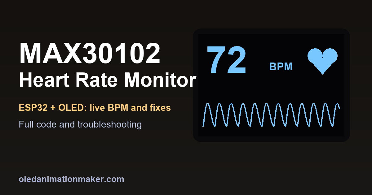
A MAX30102 heart rate monitor is one of the nicest sensor projects you can build on a tiny OLED screen. You rest a finger on a small board, and a few seconds later the screen shows a beating heart, a live pulse wave and your beats per minute. This guide builds that with an ESP32, a MAX30102 module and a 0.96 inch SSD1306 display, with a full sketch and a fix for every problem that usually goes wrong.
Pulse sensor builds are popular right now. Adafruit's blog listed an OLED pulse oximeter in a roundup of ESP32 projects earlier this month. Most tutorials stop at printing numbers in the Serial Monitor, or they leave you stuck when the sensor is "not found" or the reading is wrong. This page goes further: a clean screen layout, an animated heart, and a troubleshooting list.
Important. This is a hobby project, not a medical device. It cannot diagnose anything, and its numbers must never be used to make a health decision. If you are worried about your heart, talk to a doctor.
Quick answer. Wire the MAX30102 and the SSD1306 to the same four ESP32 pins: 3V3, GND, SDA (GPIO 21) and SCL (GPIO 22). Install the SparkFun MAX3010x and Adafruit SSD1306 libraries, paste the sketch below, and rest a fingertip lightly on the sensor. The sketch reads the infrared light the finger reflects, finds each beat, and shows the average BPM.
How the MAX30102 measures a heartbeat
The MAX30102 has two tiny LEDs, one red and one infrared, and a light sensor next to them. When you rest a fingertip on it, the sensor measures how much light bounces back. Blood absorbs light. Each time your heart pushes a pulse of blood into the finger, a little more light is absorbed, and the reading dips slightly.
That dip is the signal. The reading is a big, steady number, around 90,000 here, with a tiny wobble of a few hundred riding on top. The wobble is your pulse. The sketch finds the peaks of the wobble, measures the time between them, and turns that into beats per minute.
The chip can also compare red and infrared light to estimate blood oxygen, called SpO2. This guide leaves that out on purpose. Oxygen readings need careful calibration, and cheap modules are not reliable enough to trust. Heart rate from the infrared signal alone is simpler and more honest.
What you need
- An ESP32 board. A classic ESP32 DevKit V1 costs roughly $6 to $10 on Amazon US. An ESP32-C3 SuperMini also works.
- A MAX30102 module. Expect about $4 to $10. The quality of these boards varies a lot, so buy from a seller with good reviews.
- A 0.96 inch 128x64 I2C OLED with the SSD1306 chip, about $5 to $8.
- Jumper wires. Eight female-to-female wires for bare boards, or a breadboard and male-to-male wires.
- A USB data cable for power and uploading.
Wire the MAX30102 and the OLED to the ESP32
Both modules use I2C, a two-wire bus. They can share the same two data wires because each answers to its own address: the OLED at 0x3C and the sensor at 0x57. Power both from the 3.3 V pin.
| Module pin | MAX30102 label | OLED label | ESP32 DevKit V1 | ESP32-C3 SuperMini |
|---|---|---|---|---|
| Power | VIN | VCC | 3V3 | 3V3 |
| Ground | GND | GND | GND | GND |
| Clock | SCL | SCL | GPIO 22 | GPIO 9 |
| Data | SDA | SDA | GPIO 21 | GPIO 8 |
| Not used | INT, RD, IRD | none | leave empty | leave empty |
Read the labels printed on your own boards before you connect power, because some modules list pins in a different order. If your OLED stays blank later, the SSD1306 blank screen fixes include an I2C scanner. The ESP32 OLED wiring guide shows the same two data wires with more detail if the OLED is new to you.
Install the ESP32 core and the libraries
- In the Arduino IDE, open Tools > Board > Boards Manager, search for esp32 and install esp32 by Espressif Systems. Pick ESP32 Dev Module for a DevKit V1.
- Open Sketch > Include Library > Manage Libraries. Search for SparkFun MAX3010x and install SparkFun MAX3010x Pulse and Proximity Sensor Library. It supports the MAX30102 as well as the MAX30105.
- Search for Adafruit SSD1306 and install it. Accept the offer to install Adafruit GFX and Adafruit BusIO too.
The beat detector in this sketch comes with the SparkFun MAX3010x library, in a file called heartRate.h. You do not need to install anything extra for it. The 128x64 I2C OLED example code explains the drawing calls, such as drawLine() and fillCircle(), if you want to change the layout.
The MAX30102 heart rate monitor code
Paste this into a new sketch. The lines marked CHANGE are the ones you may need to adjust: the two I2C pins, the OLED address, the finger threshold and the sensor LED power.
// MAX30102 heart rate monitor on an SSD1306 OLED (ESP32)
// Libraries: SparkFun MAX3010x, Adafruit SSD1306, Adafruit GFX
#include <Wire.h>
#include <Adafruit_GFX.h>
#include <Adafruit_SSD1306.h>
#include "MAX30105.h"   // SparkFun library (also drives the MAX30102)
#include "heartRate.h"  // checkForBeat()

// ---------- Settings ----------
const int SDA_PIN = 21;           // CHANGE: DevKit V1 = 21, C3 SuperMini = 8
const int SCL_PIN = 22;           // CHANGE: DevKit V1 = 22, C3 SuperMini = 9
const uint8_t OLED_ADDR = 0x3C;   // CHANGE to 0x3D if your screen needs it
const long FINGER_MIN = 50000;    // CHANGE: raw IR value that means "finger on the sensor"
const byte LED_POWER = 60;        // CHANGE: sensor LED brightness 0-255 (60 is about 12 mA)

const int SAMPLE_RATE = 400;      // samples per second inside the sensor
const int SAMPLE_AVG = 4;         // the sensor averages 4 samples, so we get 100 per second
const float SAMPLE_MS = 1000.0f * SAMPLE_AVG / SAMPLE_RATE;  // 10 ms between samples

const int SCREEN_W = 128, SCREEN_H = 64;
Adafruit_SSD1306 display(SCREEN_W, SCREEN_H, &Wire, -1);
MAX30105 sensor;

// ---------- Heart rate state ----------
const byte RATE_SIZE = 5;         // average the last 5 beats
float rates[RATE_SIZE];
byte rateCount = 0, rateSpot = 0;
unsigned long sampleClock = 0;    // counts samples, so beat timing does not depend on screen drawing
unsigned long lastBeatClock = 0;  // sampleClock value at the last beat (0 = none yet)
unsigned long beatFlashMs = 0;    // when the heart icon last pulsed
int bpm = 0;                      // averaged BPM, 0 = no reading yet
bool fingerOn = false;

// ---------- Waveform state ----------
const int WAVE_Y = 36, WAVE_H = 28;   // the wave uses the bottom 28 rows
uint8_t wave[SCREEN_W];
int wavePos = 0;
byte waveSkip = 0;
float dcLevel = 0, amp = 50;

void resetReading() {
  bpm = 0; rateCount = 0; rateSpot = 0; lastBeatClock = 0;
  for (int i = 0; i < SCREEN_W; i++) wave[i] = WAVE_H / 2;
}

void showMessage(const char* line1, const char* line2) {
  display.clearDisplay();
  display.setTextSize(1);
  display.setTextColor(SSD1306_WHITE);
  display.setCursor(0, 20); display.println(line1);
  display.setCursor(0, 34); display.println(line2);
  display.display();
}

void setup() {
  Serial.begin(115200);
  Wire.setPins(SDA_PIN, SCL_PIN);          // I2C pins, used by both modules
  if (!display.begin(SSD1306_SWITCHCAPVCC, OLED_ADDR)) {
    Serial.println("OLED not found: check wiring and the address");
    while (true) delay(1000);
  }
  if (!sensor.begin(Wire, I2C_SPEED_FAST)) {
    Serial.println("MAX30102 not found: check wiring");
    showMessage("MAX30102 not found", "Check the wiring");
    while (true) delay(1000);
  }
  // LED power, sample average, LED mode (2 = red + IR), sample rate, pulse width, ADC range
  sensor.setup(LED_POWER, SAMPLE_AVG, 2, SAMPLE_RATE, 411, 4096);
  resetReading();
}

void handleSample(long ir) {
  // Serial.println(ir);   // uncomment and open the Serial Plotter to see raw values

  if (ir < FINGER_MIN) {                 // no finger: forget everything
    if (fingerOn) { fingerOn = false; resetReading(); }
    return;
  }
  if (!fingerOn) { fingerOn = true; dcLevel = ir; amp = 50; }
  sampleClock++;

  // Waveform: a slow average is the steady level, what is left is the pulse
  dcLevel += (ir - dcLevel) * 0.05f;
  float ac = ir - dcLevel;
  amp = max(amp * 0.995f, fabsf(ac));      // auto-scale, shrinks slowly
  if (amp < 20) amp = 20;
  if (++waveSkip >= 3) {                   // keep every 3rd sample, about 33 points per second
    waveSkip = 0;
    // the raw value dips on a beat, so flip it to make each beat a peak
    float v = WAVE_H / 2 + (ac / amp) * (WAVE_H / 2 - 2);
    wave[wavePos] = (uint8_t)constrain((int)v, 0, WAVE_H - 1);
    wavePos = (wavePos + 1) % SCREEN_W;
  }

  // Beat detection (Maxim algorithm from the SparkFun library)
  if (checkForBeat(ir)) {
    if (lastBeatClock != 0) {
      float ms = (sampleClock - lastBeatClock) * SAMPLE_MS;
      float b = 60000.0f / ms;
      if (b > 40 && b < 180) {          // ignore impossible values
        rates[rateSpot] = b;
        rateSpot = (rateSpot + 1) % RATE_SIZE;
        if (rateCount < RATE_SIZE) rateCount++;
        float sum = 0;
        for (byte i = 0; i < rateCount; i++) sum += rates[i];
        bpm = (int)(sum / rateCount + 0.5f);
      }
    }
    lastBeatClock = sampleClock;
    beatFlashMs = millis();
  }
  // No beat for 5 seconds: the reading is stale
  if (lastBeatClock != 0 && (sampleClock - lastBeatClock) * SAMPLE_MS > 5000) {
    bpm = 0; rateCount = 0; rateSpot = 0; lastBeatClock = 0;
  }
}

void drawHeart(int cx, int cy, int r) {
  display.fillCircle(cx - r, cy, r, SSD1306_WHITE);
  display.fillCircle(cx + r, cy, r, SSD1306_WHITE);
  display.fillTriangle(cx - 2 * r + 1, cy + r / 3, cx + 2 * r - 1, cy + r / 3,
                       cx, cy + 2 * r + r / 2, SSD1306_WHITE);
}

void drawScreen() {
  display.clearDisplay();
  display.setTextColor(SSD1306_WHITE);
  if (!fingerOn) {
    display.setTextSize(1);
    display.setCursor(14, 18); display.print("Rest a finger on");
    display.setCursor(14, 32); display.print("the sensor");
    drawHeart(104, 28, 5);
    display.display();
    return;
  }
  display.setTextSize(3);
  display.setCursor(0, 4);
  if (bpm > 0) display.print(bpm); else display.print("--");
  display.setTextSize(1);
  display.setCursor(60, 20); display.print("BPM");
  bool pulse = millis() - beatFlashMs < 140;   // heart grows for 140 ms after each beat
  drawHeart(108, 14, pulse ? 7 : 5);

  // The pulse wave, oldest point on the left
  for (int i = 1; i < SCREEN_W; i++) {
    int a = wave[(wavePos + i - 1) % SCREEN_W];
    int b = wave[(wavePos + i) % SCREEN_W];
    display.drawLine(i - 1, WAVE_Y + a, i, WAVE_Y + b, SSD1306_WHITE);
  }
  display.display();
}

void loop() {
  sensor.check();                          // pull new samples from the sensor's FIFO
  while (sensor.available()) {
    long ir = sensor.getFIFOIR();
    sensor.nextSample();
    handleSample(ir);
  }
  static unsigned long lastDraw = 0;
  if (millis() - lastDraw >= 40) {         // about 25 screen updates per second
    lastDraw = millis();
    drawScreen();
  }
}
When it works, you will see "Rest a finger on the sensor" and a small heart. Put a fingertip lightly on the sensor window. After a few beats, the heart pulses, the wave starts to move, and the BPM number appears. Take your finger off and it returns to the prompt.
How the sketch works, step by step
- Read the sensor often. The sensor stores its readings in a small queue. The loop empties that queue every pass, so no sample is lost while the screen draws.
- Check for a finger. A raw infrared value below
FINGER_MINmeans nothing is on the sensor, so the sketch clears the old reading. - Draw the wave. A slow average gives the steady level. The leftover wobble is scaled to fit 28 pixels, and every third point goes on screen.
- Find the beats.
checkForBeat()from the SparkFun library spots each pulse peak in the signal. - Turn timing into BPM. The time between two beats is counted in samples, 10 ms each. BPM is 60,000 divided by that time in milliseconds.
- Average the last 5. One bad beat does not make the number jump, and values outside 40 to 180 are ignored.
Counting samples instead of reading millis() matters. Drawing the screen takes about 25 ms, so a beat found a little late would shift the timing and make the BPM jitter. A sample count stays exact.
I checked every library call in this sketch against the SparkFun library source. I also ran the same beat logic against a simulated pulse signal at 50, 60, 72, 90, 110 and 150 BPM, and the average landed within 1 BPM each time. That is a software check only. Real fingers are messier, so use the fixes below if your numbers look odd.
Tune the finger threshold and LED power
Two numbers decide how well this works on your board. FINGER_MIN is the raw infrared value that means "finger present". LED_POWER sets how bright the sensor's LEDs are. Both depend on your module and your skin, so check them once.
- Remove the
//from theSerial.println(ir)line at the top ofhandleSample(). - Open Tools > Serial Plotter at 115200 baud and rest a finger on the sensor.
- Note the steady value with a finger on, and the value with nothing on it.
- Set
FINGER_MINhalfway between the two numbers.
| What you see | Change this |
|---|---|
| The value with a finger is always below 50,000 | Raise LED_POWER (try 80 to 120) or lower FINGER_MIN. |
| The value is stuck at its maximum and the wave is flat | Lower LED_POWER (try 30 to 40). The sensor is saturated. |
| The wave is tiny | Press a little harder, warm your finger, and keep still. |
| The BPM is double the real value | Press more lightly and lower LED_POWER a little. |
The library's own comments say the default LED power of 0x1F is about 6.4 mA. This sketch uses 60, which is roughly 12 mA, so it works on more fingers. Higher power also uses more current, which matters on a battery. The OLED power consumption guide shows how to estimate that.
Troubleshooting the MAX30102 heart rate monitor
- Problem: "MAX30102 not found". Why: loose wires, SDA and SCL swapped, no power, or a faulty module. Fix: check each wire, and run an I2C scanner. You should see 0x57 for the sensor and 0x3C for the OLED.
- Problem: the scanner never shows 0x57 on a new module. Why: some cheap boards are designed badly. Forum reports describe boards whose I2C pull-up resistors are tied to the 1.8 V rail instead of 3.3 V. Fix: try a second module from another seller, or look for a solder jumper that picks the pull-up voltage.
- Problem: the OLED stays black. Why: a wrong address, wrong pins, or swapped SDA and SCL. Fix: try 0x3D, and check the wiring against the table. The blank screen guide lists every cause.
- Problem: it stays on "Rest a finger on the sensor". Why: the raw value never passes
FINGER_MIN. Fix: print the raw value, as shown above, and lowerFINGER_MINor raiseLED_POWER. - Problem: the BPM never appears, but the wave moves. Why: the beat detector sees no clean peaks. Fix: keep the finger still for 10 seconds, press lightly, and shield the sensor from bright room light.
- Problem: the BPM jumps between values. Why: movement, pressing too hard, or cold fingers. Fix: rest the hand on a table, press as lightly as you can while still touching the window, and warm your hands first.
- Problem: the BPM is double or half the real value. Why: the detector counted a small second bump in each pulse, or missed a beat. Fix: lower
LED_POWERa little and press lightly. The average of 5 beats evens out one-off misses. - Problem: the wave looks jerky. Why: the I2C bus is slow, or something in
loop()takes too long. Fix: keep extra work short and do not add a longdelay(). - Problem: the board restarts at random. Why: the USB port cannot supply enough current. Fix: use a short, good cable and a wall charger, not a laptop hub.
How accurate is it, and what it cannot do
A MAX30102 module and this sketch are good for learning how optical heart rate sensing works. They are not accurate enough for health use. Hobby sensors are sensitive to how hard you press, how warm your finger is, how much you move and how much ambient light reaches the sensor. A smartwatch or a medical pulse oximeter will often give a different number, and they should be trusted over this project.
Treat the screen as a demo. It is a good way to see your pulse change after you climb a flight of stairs, and a good way to learn about sensors and signal processing. Do not use it to monitor your health, a medical condition, or another person. If you need a reliable reading, use a certified device.
Make it your own
- A bigger beat animation. Draw a custom heart or animal in the OLED Animation Maker, export the frames, and play them each time
pulseis true. - A dashboard. Add a bar for the average and a small chart. The OLED dashboard guide has ready-made bars and gauges.
- A handy clock. Show the time when no finger is on the sensor. The ESP32 OLED clock has the NTP code.
- Keep the screen healthy. If the display stays on for long periods, dim it or turn it off when no finger is detected, to avoid burn-in.
- Try it in the browser first. The OLED simulator lets you test layouts before you wire anything.
Next steps
- Add a custom boot logo using the Image to Byte Array tool.
- Make the same layout work on a different board with the ESP32 OLED animation guide.
- Build an animated companion that reacts to touch, like the ESP32 desk robot with OLED eyes.
Frequently asked questions
Can this sketch measure blood oxygen (SpO2)?
No. The sketch only shows heart rate. Blood oxygen needs careful calibration and the cheap MAX30102 boards are not reliable enough for it, so this guide leaves it out on purpose.
Is a MAX30102 heart rate monitor accurate enough for health use?
No. It is a learning and hobby project, not a medical device. Movement, pressure, cold fingers and room light all change the reading. Never use it to make a health decision.
Why does my MAX30102 show double the heart rate?
The beat detector is counting a small second bump in each pulse. Press more lightly, lower LED_POWER a little, and keep the finger still so only the main peak is counted.
Can I use the MAX30102 with an Arduino Uno?
Yes, the SparkFun library works on an Uno and the I2C pins are A4 and A5. The 128x64 OLED buffer takes 1 KB of the Uno's 2 KB of RAM, so keep the sketch small and shrink the waveform array.
Do I need the INT pin on the MAX30102?
No. The INT pin tells the board when new data is ready, but this sketch simply reads the sensor often. Leave INT, RD and IRD unconnected.
Related guides
- ESP32 OLED clock: NTP time, big digits and rolling animation
- ESP32 OLED animation: SSD1306 wiring and code
- Fix an SSD1306 OLED blank screen
- Arduino OLED dashboard: gauges and progress bars
- OLED power consumption and battery life
Free tools: Lithophane Maker for flat, curved, heart, round and cylinder lamp lithophanes, the Shadow Box Lamp Generator for wall shadow lamps, Text to STL for names and keychains, and 3MF to Web to show your prints on a website. See all tools.